


Fluidics
Reduce prototype iterations and accelerate time to market with fluidic simulations that analyze performance before you build your system.
IDEX Health & Science uses Computational Fluid Dynamics (CFD) modeling to analyze how your fluidic system will perform before you commit to physical prototypes. By simulating flow rate, pressure, mechanical stress, and other fluidic behaviors up front, CFD lets instrument developers characterize hardware functionality in weeks instead of months. The result: fewer prototype iterations, lower development costs, and a faster path from concept to a production-ready fluidic system.
CFD modeling is a simulation method that predicts how fluid moves through a system before any physical parts are built. Engineers use it to evaluate flow rate, pressure, mechanical stress, and other fluidic behaviors across the geometry of a proposed design.
Without preemptive fluidic analysis, instrument development often falls into a trial-and-error pattern, or “cook-and-look” approach: you design the system, order the parts, build the prototype, and only learn what works after it is on the bench. This method inevitably leads to multiple prototype iterations, adding time and cost to each cycle. Problems uncovered late are usually the most expensive to fix.
CFD modeling replaces that physical-iteration cycle with virtual analysis up front. By the time you commit to a prototype, you already know how the system is likely to behave.
CFD modeling is most valuable when the cost of physical iteration is high, when system behavior is hard to predict, or when multiple design variants need to be compared before committing to hardware. The following scenarios are common signals that fluidic simulation should be part of your development process.
 Get Expert Guidance on Your Custom Fluidic Instrument Design

A cross-section and surface view of mechanical stress distribution in a CFD-modeled component: Slice von Mises stress (psi); surface von Mises stress (psi).

Pressure, shear stress, and velocity flow across surfaces in a CFD-modeled fluidic system. Surface pressure (psi); surface shear stress (psi); arrow volume velocity field (spatial frame); surface contact pressure (psi).
The figures above show typical CFD outputs from IDEX Health & Science fluidic projects. Our engineers use CFD modeling to characterize fluid behavior across the geometry of your system, evaluating the following factors before any parts are built:

Predict how pressure builds across the flow path and where forces concentrate under operating conditions, so the design can hold up at the pressures your system requires.

Model how fluid distributes across channels and how reagents combine, supporting consistent delivery and accurate sample preparation.

Identify where components experience stress that could affect long-term reliability or trigger unexpected failures before they appear in physical testing.

Locate dead zones where fluid stagnates, which can contribute to carryover, contamination, or inconsistent measurements.

Visualize how residue, sample, or reagent can migrate between flow paths, so the geometry can be optimized to prevent unwanted mixing.
CFD modeling with IDEX Health & Science delivers integrated fluidics that are fully tested for functionality and performance, ready to be dropped into your instrument right out of the box. By characterizing system behavior up front, CFD lets developers move through prototyping in weeks instead of months, reducing iterations and accelerating time to market. CFD confirms three critical factors in your fluidic design:

CFD confirms your design holds pressure under operating conditions before any parts are manufactured, so you know the system will perform at the pressures your application requires.

CFD identifies flow restrictions and bottlenecks in the modeling stage, so you can resolve them in the design rather than after prototypes are built.

Stress and pressure simulation locates failure risks early, helping you design out leak points before they appear in physical testing.
Explore a CFD Modeling Partnership For Your Instrument
CFD modeling is one part of a broader fluidic engineering approach at IDEX Health & Science. Our technical team combines computational simulation, physical testing, and decades of fluidic design expertise to evaluate your project from multiple angles before parts are built. This combined approach lets you move from concept to confirmed design with fewer surprises and a clearer path to manufacturable, integration-ready fluidics.

Alongside CFD, our engineers use FMEA, FEA, DFX, Tolerance Analysis, DOE, and Weibull-based lifetime demonstration testing to evaluate fluidic designs across performance, manufacturability, and reliability.
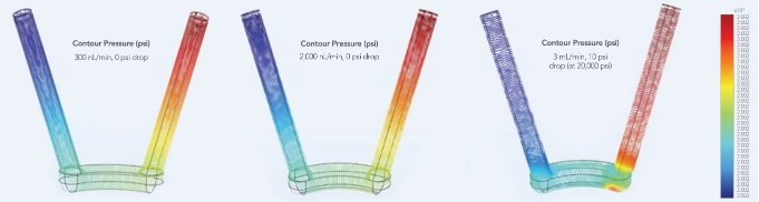
Pressure drops at 300 nL/min, 2,000 nL/min, and 3.0 mL/ min.

Once designs move into prototyping, IDEX Health & Science verifies real-world performance using surface analysis equipment, including digital optical microscopes, white-light interferometric optical profilometers, and Scanning Electron Microscopy (SEM). More advanced analyses, such as Tunneling Electron Microscopy (TEM) and Focused Ion Beam Milling (FIB), are available through certified partner laboratories.
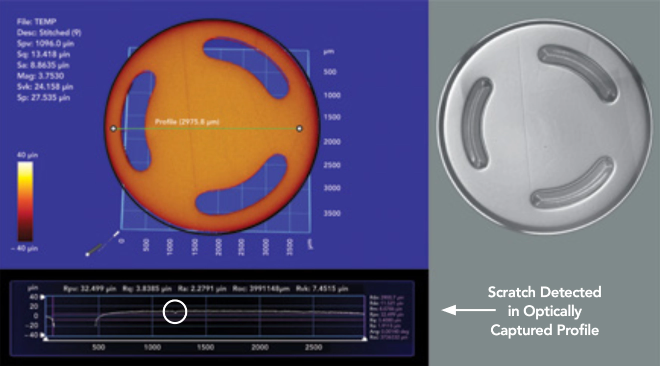
Surface analysis of valve rotor seal with optical profilometer and microscope.

With component-, subsystem-, and application-level engineers under one roof, IDEX Health & Science evaluates fluidic performance within the full optofluidic pathway. That perspective helps identify integration risks that might be missed when CFD is run on a single component in isolation.
CFD modeling is part of how IDEX Health & Science designs and validates fluidic systems across multiple product families and applications. The following examples show where CFD has been applied to solve real engineering challenges for OEM instrument developers.

CFD modeling is used to evaluate port-to-port volume, pressure drop, and flow path geometry in rotary shear valves, with simulations run across nominal alignment and small misalignments at flow rates from 300 nL/min to 3 mL/min.

CFD analyzes pressure drop across check valve cartridges to identify fluid movement and how internal geometry changes affect flow restriction and turbulence, enabling design adjustments before manufacturing. LEARN MORE

CFD modeling evaluates and optimizes fluidic geometries within LC-MS flow rate and system pressure ranges, comparing wide-radius tube-in-manifold designs against legacy etched channel geometries to predict chromatographic performance before mechanical prototyping.

CFD mitigates risk by evaluating fluidic resistance and flow path design across bonded manifolds that integrate multiple components such as shear valves, solenoid valves, sensors, and pumps into a single subsystem.

See how IDEX Health & Science designs fluidic subsystems that mitigate risk, minimize cost, and maximize performance.
OEM teams developing fluidic instruments face decisions around design validation, partner selection, and where to invest engineering effort. Below are answers to common questions about applying CFD modeling and partnering with IDEX Health & Science.
CFD adds the most value early, before geometry is finalized and before physical parts are ordered. Running CFD during concept and feasibility stages lets you compare design variants, identify performance risks, and refine geometry while changes are still inexpensive. CFD can also be used later in development to investigate problems found in prototyping, but it pays back fastest when applied up front.
A typical engagement starts with a project request followed by a technical call to discuss your system, goals, and timeline. From there, IDEX Health & Science can establish NDAs or JDAs to protect your design, then provide a proposal that defines scope, timeline, and budget. Once aligned, the engineering team can begin CFD analysis on your fluidic design.
CFD identifies fluidic performance issues before they reach physical testing, where problems are far more expensive to diagnose and resolve. By analyzing pressure, flow, stress, and dead volume in simulation, we can catch flow restrictions, stress concentrations, and integration issues during design rather than after manufacturing, reducing both project risk and total development cost.
CFD modeling is a predictive tool, not a substitute for physical testing. Manufacturing tolerances, material behavior, surface finish, real-world contamination, and lifetime performance all require physical validation. CFD reduces how many physical iterations are needed and focuses physical testing on the variables that simulation cannot fully predict.
Both. CFD is often applied to new designs during concept and feasibility, but it can also analyze existing fluidic systems facing performance issues, integration challenges, or scale-up problems. For mature designs, CFD can identify root causes of unexpected behavior and inform targeted design adjustments.
IDEX Health & Science combines CFD with broader fluidic engineering experience, including FMEA, FEA, Tolerance Analysis, DOE, and Weibull-based lifetime testing, alongside component-, subsystem-, and application-level engineers. This combination allows IDEX Health & Science to evaluate CFD results in context and identify integration risks that might be missed when modeling a single component in isolation.

Tell us about your project, and a fluidics expert will follow up.