
Stories & Features
Explore the specifications, theory, and technology behind Semrock optical filters from IDEX Health & Science and how you can reduce cost, maintain quality, and meet your filter bill-of-materials (BOM).
Optical filters are used in numerous applications, such as fluorescence microscopy, flow cytometry, point-of-care diagnostics, Raman Spectroscopy, and Optical Coherence Tomography. This blog explores the cost drivers of implementing a custom filter into an instrument to debunk the myth that custom must mean costly.
Written by Toby Scrivener, edited by Elizabeth Bernhardt
We will cover the following topics:
You've just completed your newest product design, and the prototype works! The only problem? It’s a massive tabletop of cluttered, catalog optics, with huge unused space between. By using customized optical filters designed specifically for your instrument and technique, you can:
We discuss optical filter specifications, cost drivers, and reasons why you should explore custom filters as an additional cost-effective option.
At IDEX Health & Science, our mission is to assist customers through collaborative partnerships. As specification experts, we guide projects from concept to production, handle system upgrades, and accommodate non-standard packaging. Our focus is always on finding tailored solutions for your specific needs. The iterative process of optimizing specifications for application performance, while minimizing costs, involves input from various teams including customers, sales engineers, optical engineers, QA, and logistics.
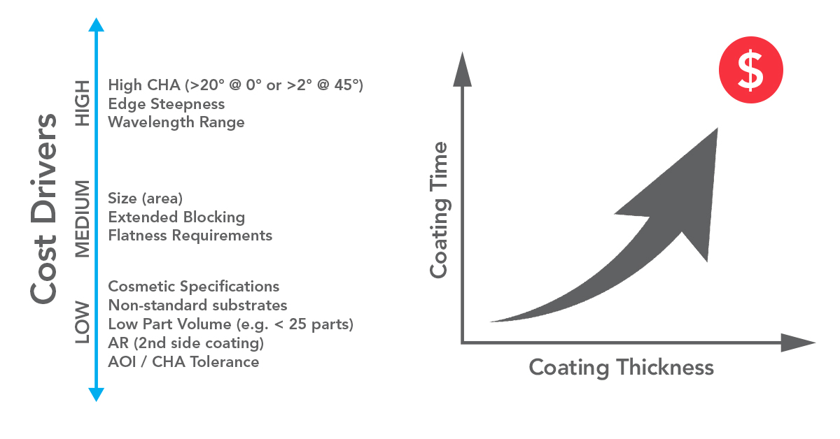
Figure 1 – Optically complex responses increase coating thickness, which increases the cost.
As shown in Figure 1, our team can divide certain specifications into high, medium, and low cost drivers. In this article, we explore these specifications and cost drivers in greater detail.
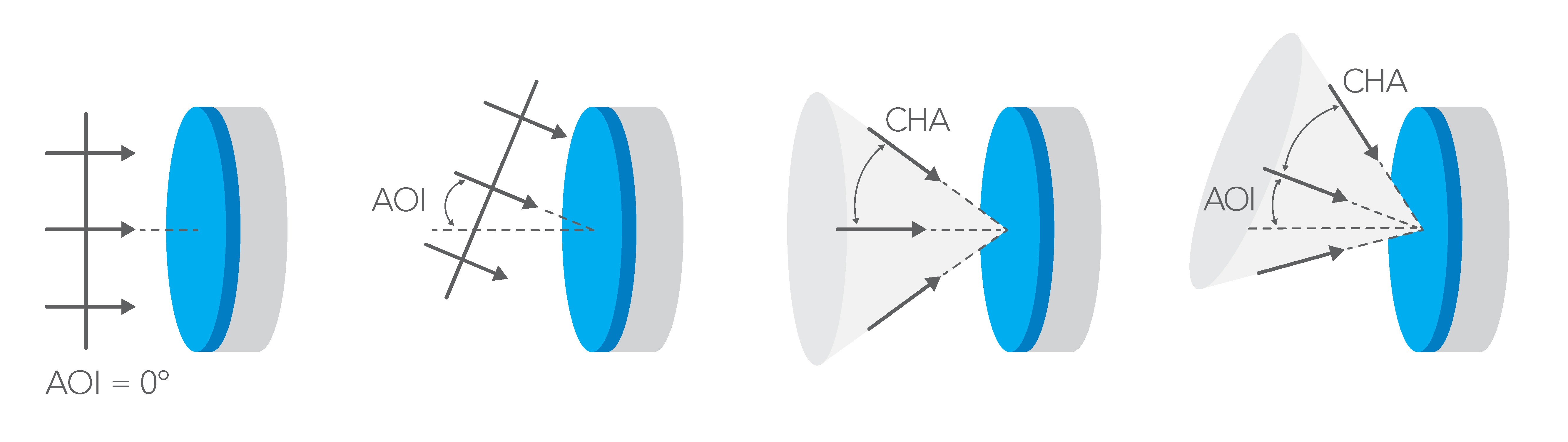
Figure 2 – The difference between angle of incidence (AOI) and cone half-angle (CHA).
When discussing filter requirements, it’s crucial to distinguish between Cone Half-Angle (CHA) and Angle of Incidence (AOI). Specifying an AOI range is not equivalent to specifying a filter with the same CHA value.
For instance, consider LL01-785 as a test subject. When we adjust the expected AOI of incoming light (Figure 3), the overall spectral performance of the MaxLine Laser Line filter remains relatively unchanged as the AOI increases from 0°, other than shifting to the blue as is expected for angle tuning. However, performance degrades rapidly with increasing CHA. Addressing this effect requires different design approaches.

Figure 3 – The effect of a varied AOI is different to a varied CHA on this MaxLine Laser Line filter.
Figure 4 (below) illustrates the consequences of using a standard catalog filter not designed for large CHA. The desired performance (green) significantly differs from the realized performance (red). In contrast, a custom filter designed for CHA (Figure
4) shows improved out-of-band blocking and edge steepness.
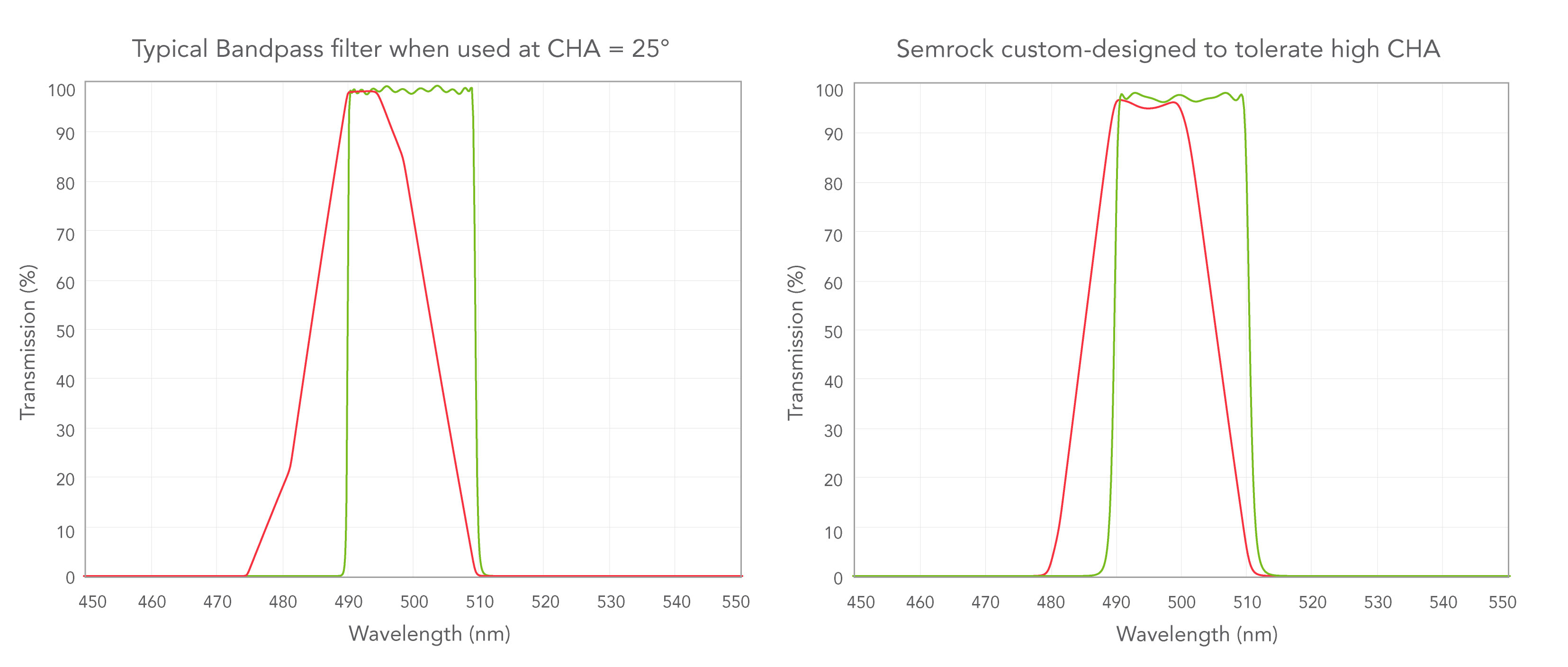
Figure 4 (above) – A standard filter without considerations to CHA shows reduced transmission performance, compared to a custom-designed filter with a high tolerance to high CHA. The green curve is CHA 0°. The red curve is CHA 25 °.
Here a high CHA would be considered as anything above 20° at 0° AOI, or >2°at 45° AOI.
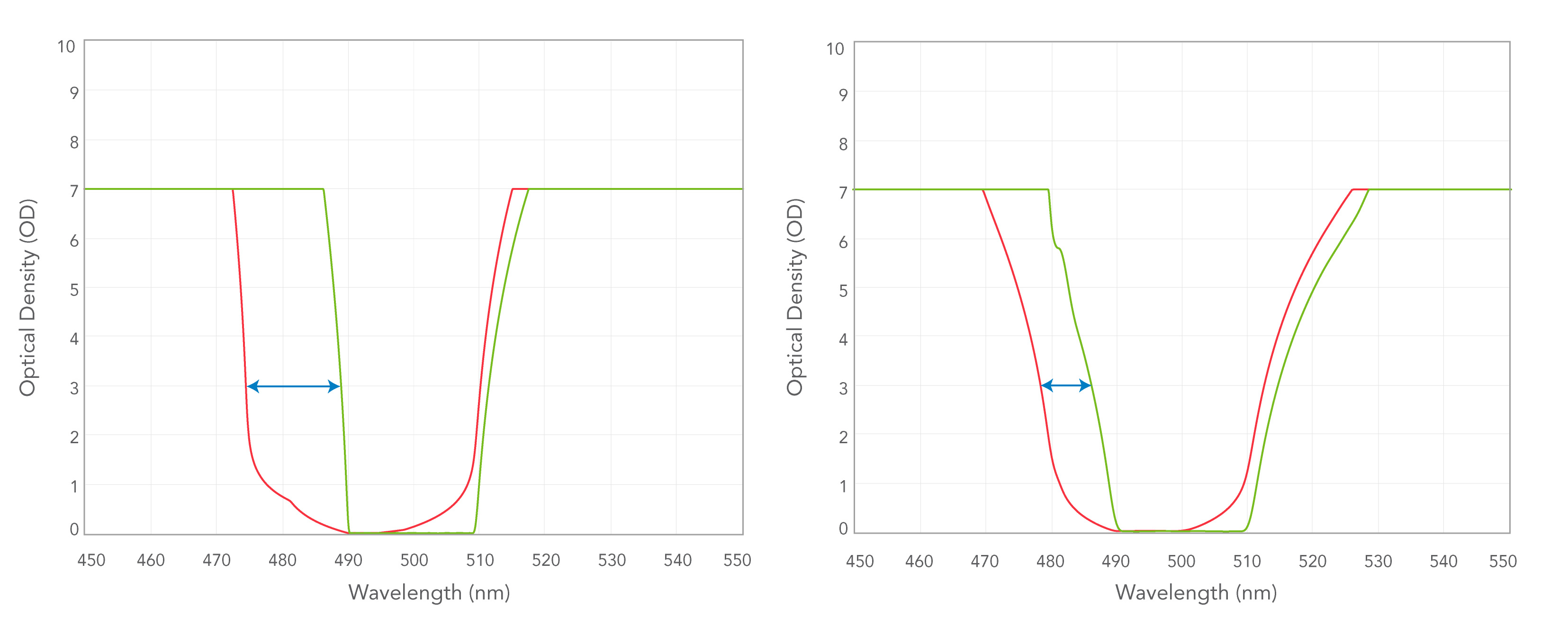
Figure 5 – Out of band blocking and edge steepness is improved when CHA is compensated with a custom filter.
Achieving steeper edges involves adding more coating layers, which increases costs and production time.
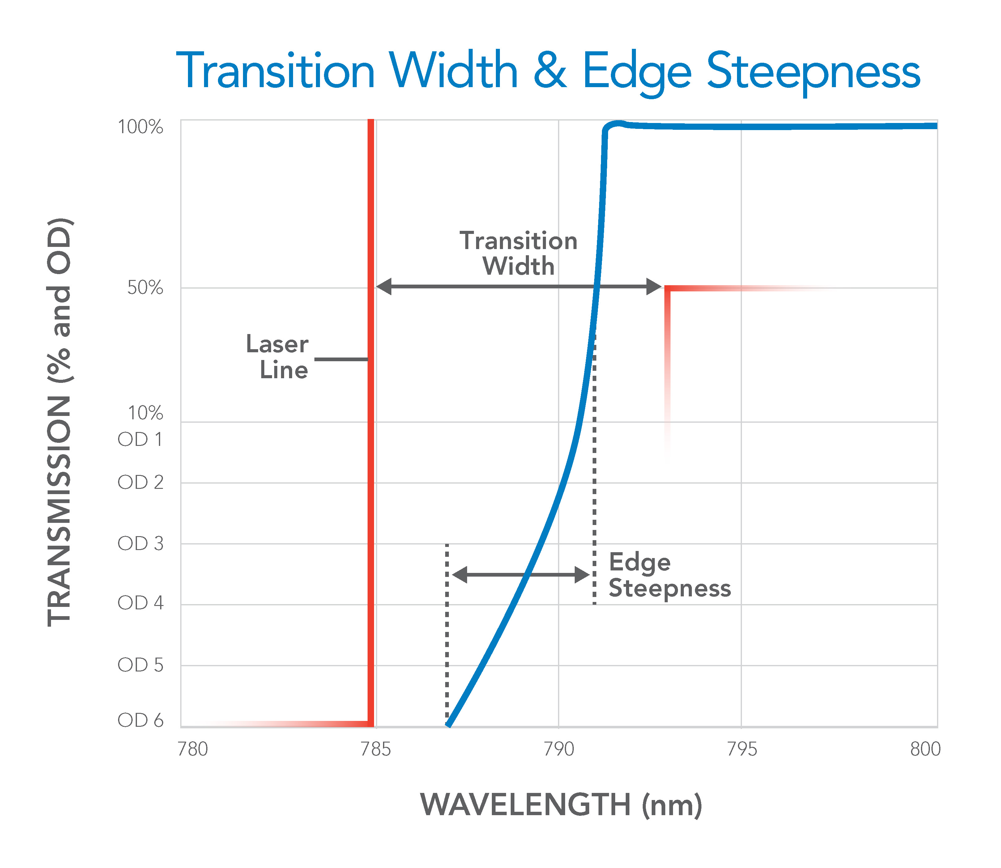
Figure 6 – The difference between Transition Width and Edge Steepness
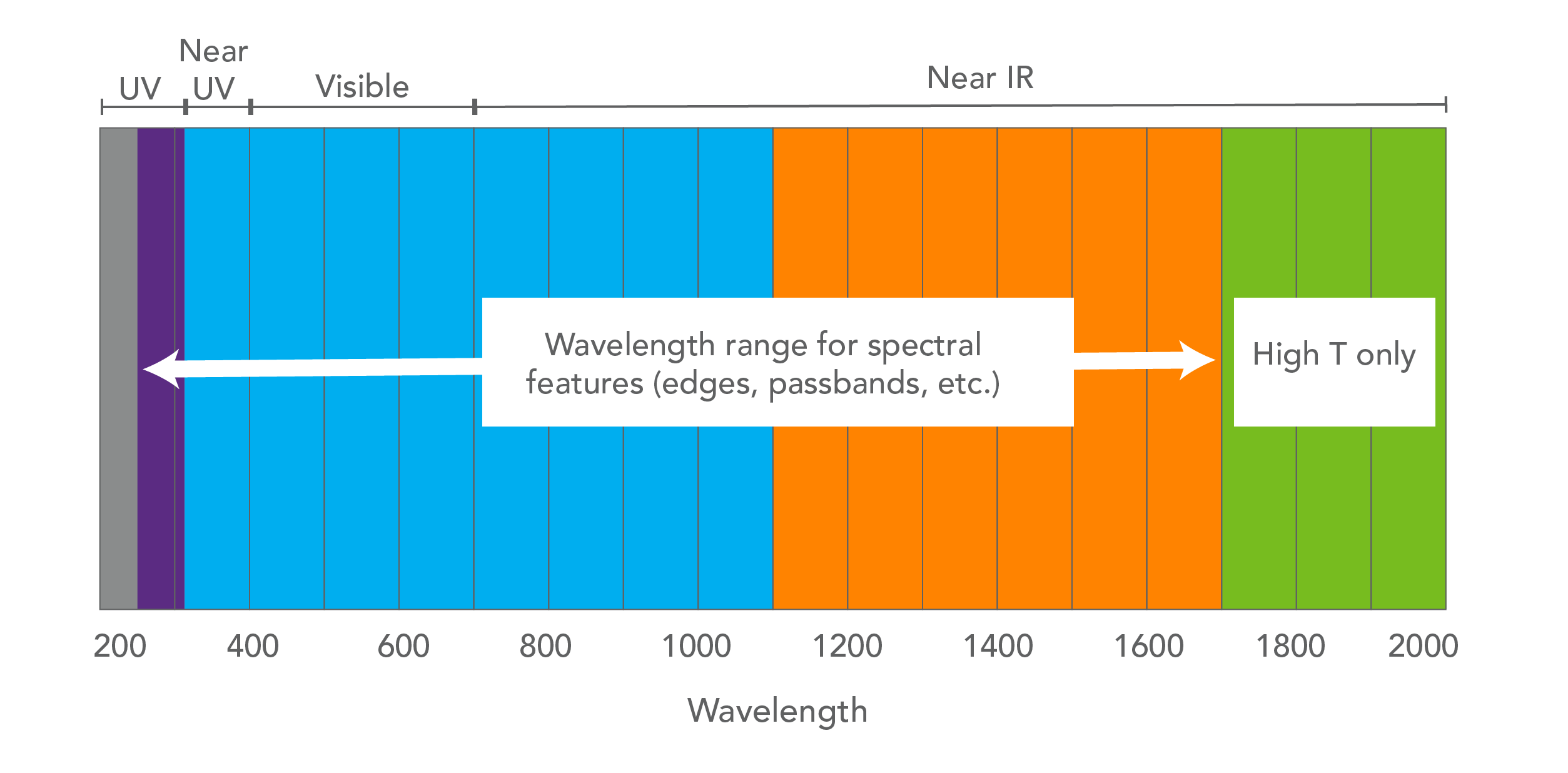
Figure 7 – The spectral zones in which your features are designed have different associated costs.
Flatness refers to the deviation of a component surface from a perfectly flat reference plane. It’s crucial in applications where maintaining beam shape or image quality matters. The Reflected Wavefront Error (RWE) measures how much a reflected wavefront deviates from a perfect one.
If you’re designing a filter with strict flatness requirements, we use a stress-compensating coating. This coating balances forces to maintain flatness, but it increases cost due to longer coating chamber time. Thicker substrates can help mitigate the cost by using the number of layers needed for the stress-compensating coating.
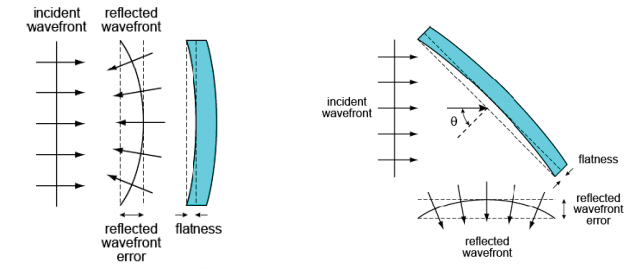
Figure 8 – Examples of RWE when the optical design does not have a stress compensating optical coating.
We analyze customer system requirements to recommend cost-effective blocking solutions. Often, customers ask for the highest level of blocking beyond their area of interest. By adopting a stepped approach and considering light levels and detector sensitivity, we can reduce costs significantly, as demonstrated in Figure 9.
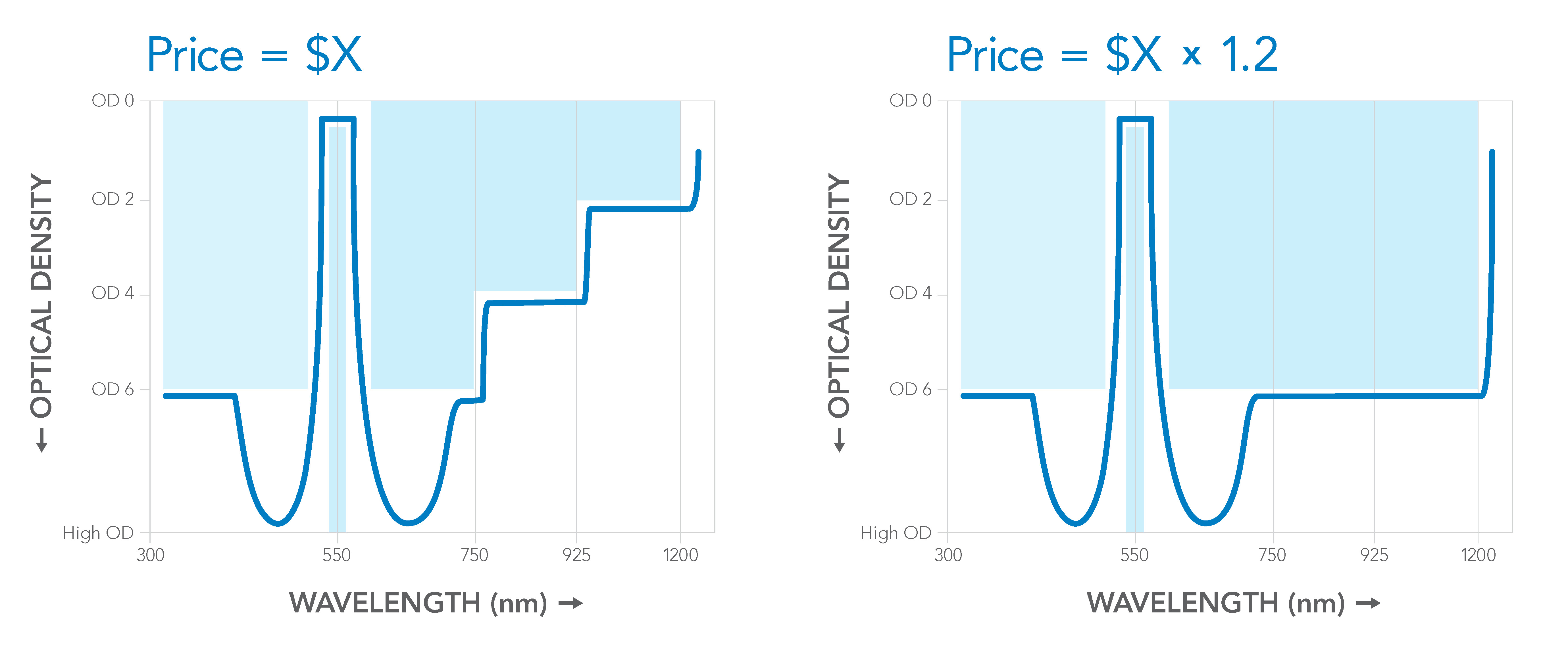
Figure 9 – a balanced approach to OD (Left) has cost savings over an extended blocking approach.
At times, filter size can be the easiest way to reduce cost. Smaller filters generally cost less than larger ones, especially when produced in large quantities. However, very small parts (under 5 mm) pose challenges in manufacturing, handling, and packaging. Larger parts can be more complex to manufacture, and costs don’t always scale linearly. During the design stage, we provide consultative advice on the optimal filter size for your application.
Scratch and Dig
All optical coatings have cosmetic imperfections no matter how they are manufactured. There are many requirements that could considered to be a cosmetic specification. One of the more significant specifications would be Scratch-Dig. We rely upon the definitions and inspection techniques established by the American National Standard Institute (ANSI) contained in standard ANSI/OEOSC OP1.002-2009.
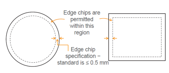
Figure 10 – The CA is necessarily limited to the outer dimension minus 2x the edge chip specification.
Edge blackening prevents or reduces light leakage through the edges of unhoused parts. Typically done by hand for small volumes, this process can be costly. However, it may not be suitable for very small parts.
For catalog parts with standard sizes (25 mm⌀ or 12.5 mm⌀), an aluminum ring housing can be used. These rings can be laser marked with custom text and an arrow indicating the direction of light propagation. Alternatively, for parts that don’t fit into a housing ring, handwritten text or a caret can serve the same purpose.
Tighter cosmetic specifications impact cost by reducing the yield but are available upon request.
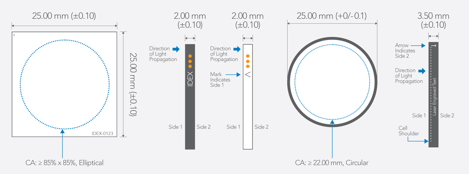
Figure 11 – The options for part marking are numerous.
If your optical filter needs a non-standard substrate, additional substrate polishing may be required to balance the polishing table. Without this, meeting target specifications is unlikely, leading to increased costs and lead time.
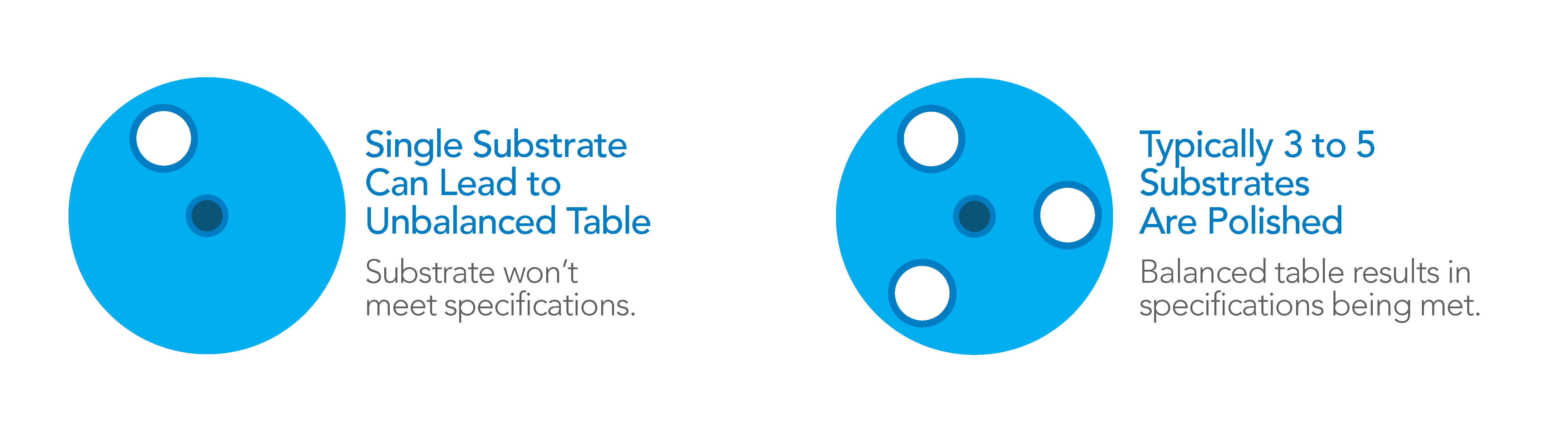
Figure 12 – Multiple substrates are required to balance the polishing process.
Applying an AR coating to one side of a substrate adds to the cost of creating an optical filter. However, since these coatings are thinner than the primary optical coating, they take less time to apply, making them a low-cost driver.
We can consider other important qualities and specifications, such as GDD Compensation, Zero Pixel Shift, and Polarization specifications. Discuss any significant considerations for your application with your sales representative.
Semrock Optical Filters from IDEX Health & Science set industry standards by combining advanced ion-beam-sputtering systems with proprietary deposition control technology, predictive algorithms, and volume manufacturing. This results in unmatched performance for biotech and analytical instrumentation.
Customer Satisfaction: Our team continuously improves supply chain management and manufacturing processes, ensuring rigorous documentation, revision control, and traceability. We maintain inventory levels to meet delivery goals.
Flexible Delivery: We offer filters to meet demanding specifications, available through blanket orders, purchasing contracts, or just-in-time delivery. Our products cater to a wide range of applications, including:
Custom Solutions: Our core strengths include:
State-of-the-Art Manufacturing: Our facilities use advanced coating chambers in cleanroom environments, with thin-film sputtering for precise, reliable optical layers. Our proprietary processes and optical monitoring technology enable high-volume production.
Performance: Semrock optical filters offer the highest transmission specifications for better contrast and faster measurements, even at UV wavelengths. They feature maximum transmission, optimized blocking, and steep edges for market-leading performance.
Durability: Semrock optical filters are resistant to humidity and temperature-induced degradation, backed by a 10-year warranty. They meet or exceed MIL-STD-810F, MIL-C-48497A, MIL-C-675C, and ISO 9022-2 standards, reducing replacement costs and ensuring reliability with a return rate of just 0.3% (industry standard is 1%).
Semrock catalog parts are world-renowned for their performance, and we offer custom-sized parts as a standard service. So, why switch to custom parts? Here are four reasons:
Whether from the first lot or the last, our filters maintain consistent spectral properties. OEM customers can rely on a secure and dependable supply line, as shown by the reproducible performance of the same filter from 40 different coating runs in Figure 13.
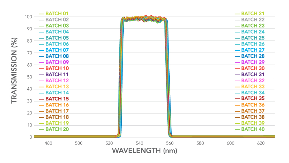
Figure 13: Forty coating runs in different coating chambers and facility locations demonstrating reproducibility and reliability.
If you want to:
Are you ready to discuss your requirements for custom or standard filters?