Using Optical Filters to Optimize Illumination in Fluorescence and Raman Systems

Introduction
IDEX Health & Science | Semrock has been delivering the ultimate in fluorescence filters for over 20 years. Our ultra-steep transition edges, deep blocking, and high transmissions have set the standard for excellence and have helped drive the creation of new, higher performance optical systems. In this Note, you will learn to use our unique products to get the most out of your fluorescence and Raman excitation designs, no matter what the light source.
Fluorescence spectroscopy, photometry, and microscopy are widely used in the biological and medical sciences. Standard fluorescence occurs when a molecule is electronically excited to a higher energy level followed by a small non-radiative decay (giving rise to the Stokes Shift, Figure 1) before emitting a photon and returning to the ground state. The Stokes Shift is responsible for the shift to longer wavelengths of the emitted light compared to the absorbed light. This spectral separation allows scientists to excite with one wavelength band of light and detect light at a separate, longer wavelength band at the same time, using a series of fluorescence filters or dispersing elements such as gratings or prisms.
No matter the light source, to achieve good signal-to-noise ratio (SNR) in a fluorescence system, any illumination light reaching the sample should strongly excite the molecules found there, and ideally transmit a wavelength range that includes the peak excitation of the fluorophores. There are three main types of illumination sources in common use for fluorescence: broadband, white-light sources (such as arc lamps), LEDs and multi-LED light engines, and lasers. We will treat these in reverse order, starting with lasers.
Optimizing Excitation with Narrow-bandpass Laser Filters
Lasers, while complicated to design from the ground up, are relatively straightforward to use. There are several types of lasers employing different lasing media and having different properties, including gas lasers, diode lasers, DPSS lasers, VCSELs, etc. Regardless of the laser medium, laser light is characterized by a narrow emission spectrum (laser Optimizing Excitation with Narrow-bandpass Laser Filters line) and a coherent beam which makes lasers ideal for multiplexing in multi-labelled fluorescence experiments. Lasers are chosen at wavelengths that maximally excite the fluorophore(s) of interest. By using a series of discrete laser wavelengths, a number of dyes can be excited and detected in a single system.
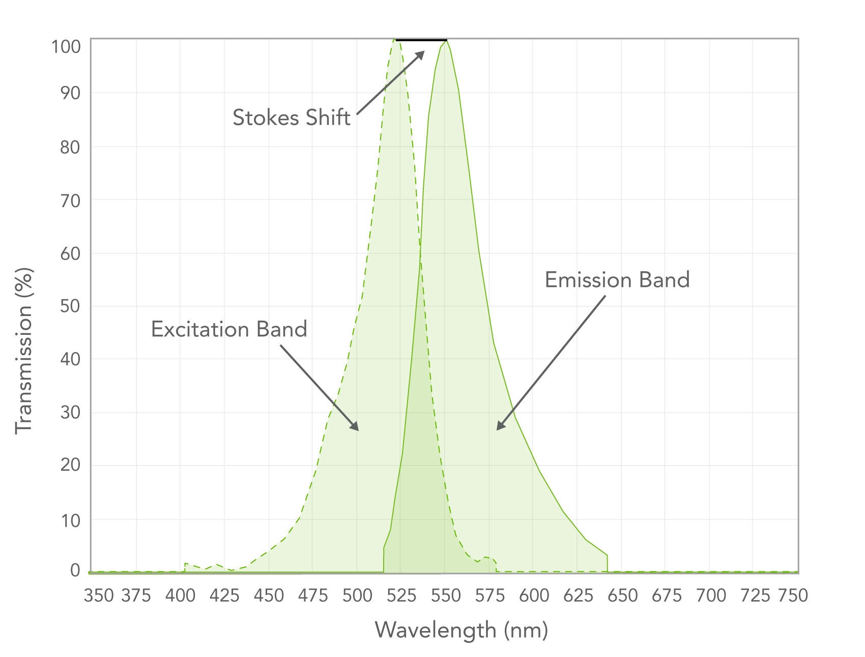
Figure 1. Excitation and emission spectra of a typical fluorophore. A combination of light source selection
Although the primary laser line dominates the light emitted, lasers often produce other emissions like amplified spontaneous emission. These are generally broader and weaker and can disrupt sensitive, low-light measurements such as weak or single-photon fluorescence and Raman spectroscopy. This underlying background emission can be detected by placing a filter that strongly blocks the laser line (longpass or narrow notch at OD6+) in front of the laser output and visualizing other colors coming through on a white card or by using a spectrometer. This spurious signal can be suppressed with a narrow bandpass filter (also referred to as laser line or clean-up filters). Semrock offers a large selection of narrow bandpass laser filters at commonly used wavelengths. These laser filters provide very high transmission at the laser wavelength, with steep transition edges and blocking over the fluorescence detection range (on the “red side”) and a more limited wavelength range on the “blue side” of the laser line.
While narrow bandwidths are desired for laser filters, there is a happy medium between bandwidth and SNR — especially important to consider if you are designing a system from the ground up. In general, the narrower the full bandwidth at half maximum (FWHM) of the laser filter, the higher the SNR. However, the laser line filter should also be wide enough to accommodate laser drift due to temperature (some lasers shift wavelength significantly as they warm up) and aging and, depending on your system, angle-of-incidence shift.
Raman applications involve laser scattering with very small Stokes Shift that correspond to vibrational modes in the molecules, measured in wavenumbers – cm-1. For this work, the edge steepness of the laser line filter should be maximized and FWHM minimized to achieve the best results for your experiment. Both Stokes and anti-Stokes detection require near-band blocking of at least OD 6 to visualize the lowest wavenumber signals in the presence of elastic (Rayleigh) scattering at the laser wavelength.
Optimizing Excitation with LED Bandpass Filters and Multichannel Illumination
LEDs have relatively narrow spectra that can be closely matched to the excitation spectrum of the fluorophores of interest (Figure 2). This and their low cost make them ideal for fluorescence systems. As with laser filters, the light from these sources must be adequately blocked over the detection wavelength range to eliminate scattered background (LED excitation) signal from reaching the detector. Semrock recommends an effective OD of about 7 at the “crossover point” (the wavelength where the excitation filter spectrum and the emission filter spectrum intersect when plotted in OD), meaning that the blocking provided by excitation and emission filter should each exceed 3.5 OD units (Figure 3).
The OD 6+ blocking range must also extend over the wavelengths where the LED emission occurs (Figure 3). Note that OD values are additive in nature, so when using several filters together, the spectra can be added to predict the total performance.
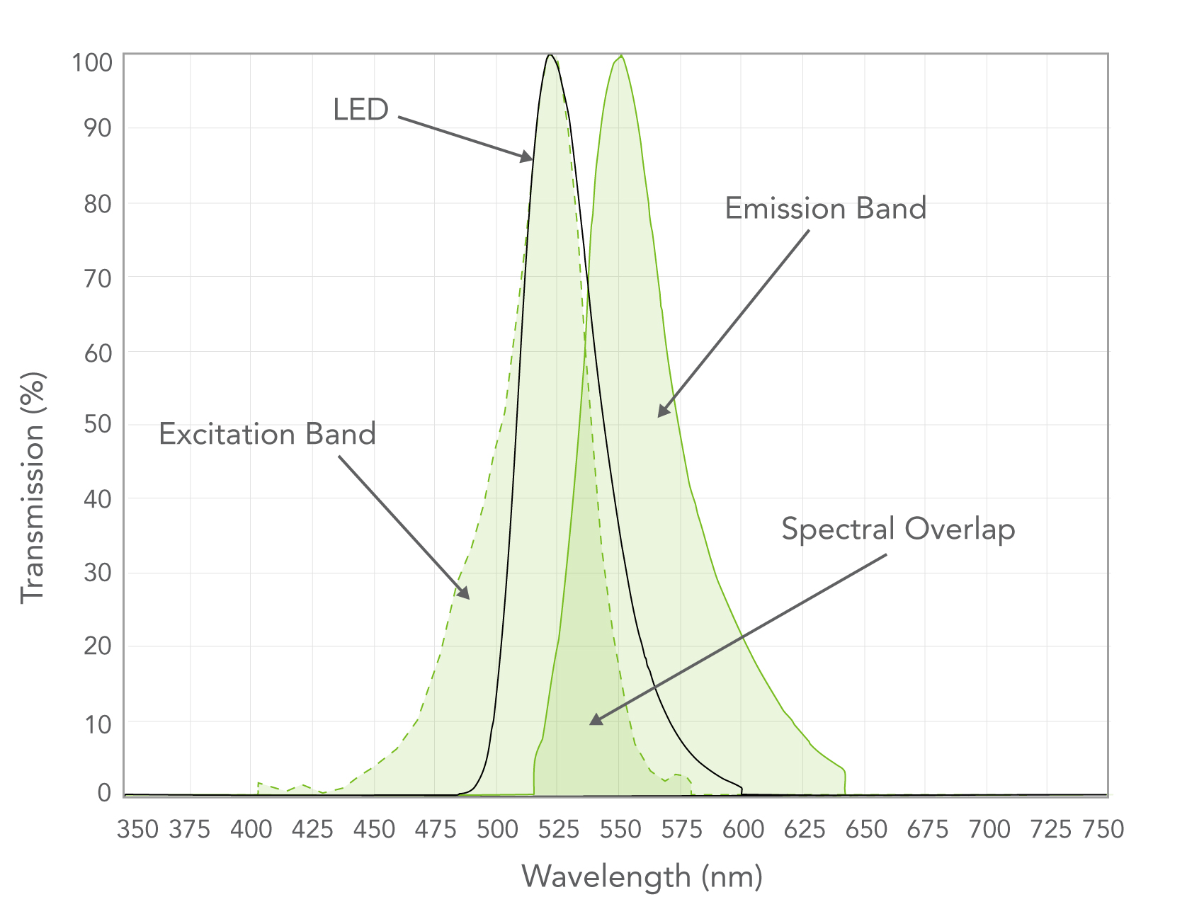 | 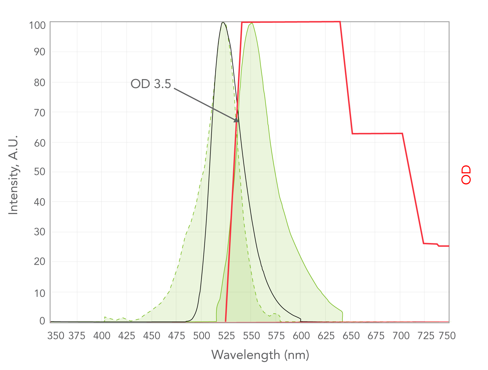 |
Figure 2. LED spectrum can be similar to the excitation spectrum, | Figure 3. Very high OD blocking is required over the emission range |
For systems using many LEDs and fluorophores, bandpass filters are required to block wavelength regions on either edge of the LED emission. Any multiplexing optical design requires extremely sharp edges for the bandpass filters to maximize SNR. There
are several strategies that can be employed for multiple LED illumination.
- Using individual bandpass filters in front of individual LEDs (or lasers) which turn on and off.
- LEDs can be programmed to pulse rapidly. Many lasers also share this property.
- The LEDs can be combined into a single beam (Figure 5a- described further below) or can be spatially separated (e.g. in a flow cytometry or PCR system as shown in Figure 4).
- This option will achieve the highest SNR regardless of filter selection because only one light source is on at a time, eliminating some categories of excitation crosstalk.
- Using individual bandpass filters in front of individual LEDs in a combined beam with simultaneous illumination.
- Beam combining can be achieved with the use of dichroic filters to align all sources to a single optical axis (Figure 5a). For a laser-based example click here.
- The success of this option will depend greatly on the overlap of the different excitation spectra of the fluorophores with the various LEDs and the relative strengths of the fluorescent signals (Figure 6).
- LEDs and fluorophores that are spectrally separated give the best results.
- Spectral unmixing algorithms can be used to eliminate crosstalk during post-processing.
- Combining the LED beams and filtering with a multiband filter for simultaneous illumination.
- This method uses the fewest filter elements; dichroics are required to merge the beams onto a single axis, and a single multiband filter positioned before the sample cleans up remaining crosstalk between LED excitation channels (Figure 5b).
- As in Point 2, success depends on the choice of LEDs and fluorophores in the system and the relative signal strengths.
- Spectral unmixing may be required in post- processing steps.
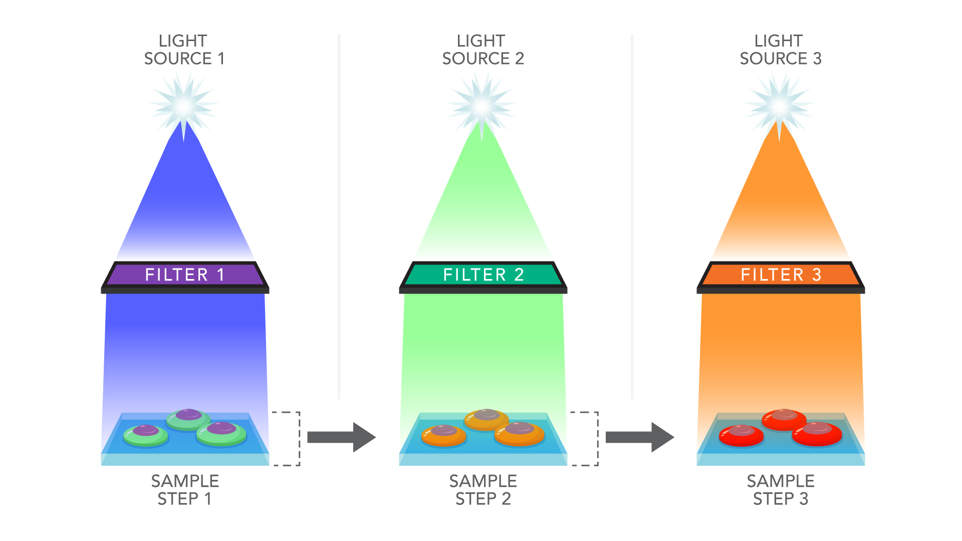 | 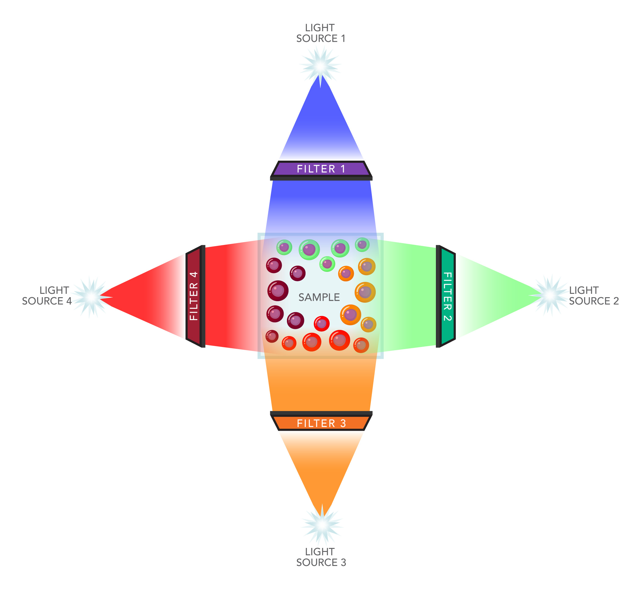 |
Figure 4. Some pulsed excitation strategies:
(a) the sample moves between the light source stations;
(b) the light sources are arranged around the sample and blink on and off.
The detector is above or below the sample plane.
Some commercially available light sources already use the methods above to deliver adjustable multiband excitation light (Figure 7). Notably, light leakage between the excitation peaks can be 0.5% or more. The SNR resulting from use of these illumination systems can be further enhanced by adding an additional multiband filter to increase blocking between channels.
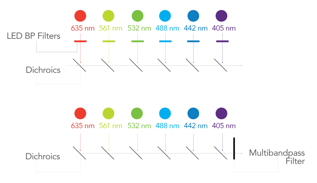
Figure 5. Combining the LED excitation sources into a single optical axis. The LEDs can continuously illuminate or work in a pulsed fashion. Crosstalk between the LED channels can be eliminated with individual bandpass filters (a) or a single multiband filter at the end of the sequence (b).
Optical Filters for Broadband Illumination
White light and broadband sources including filament- based blackbody sources, arc lamps (Xenon, Deuterium), etc. were the mainstay of fluorescence illumination for about a hundred years, and are still heavily used today
in many less sophisticated microscope systems. They are very versatile because a single source generates a large range of wavelengths. This versatility requires unique filter specifications to selectively transmit the selected light.
To effectively use a broadband source, high out-of-band blocking is required over the entire wavelength range of the detector’s response curve to eliminate cross-talk into the detection channel. This is different from LED sources, where high OD blocking is only required in wavelengths over which the LED emits.
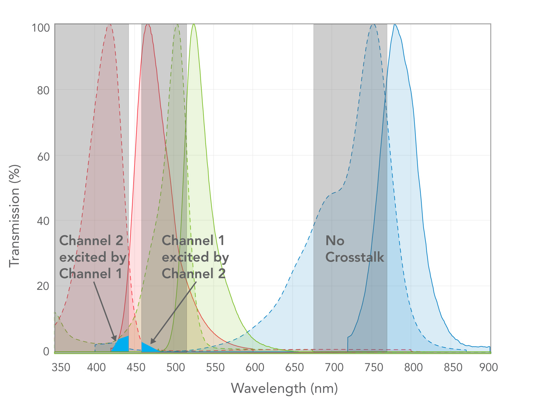 | 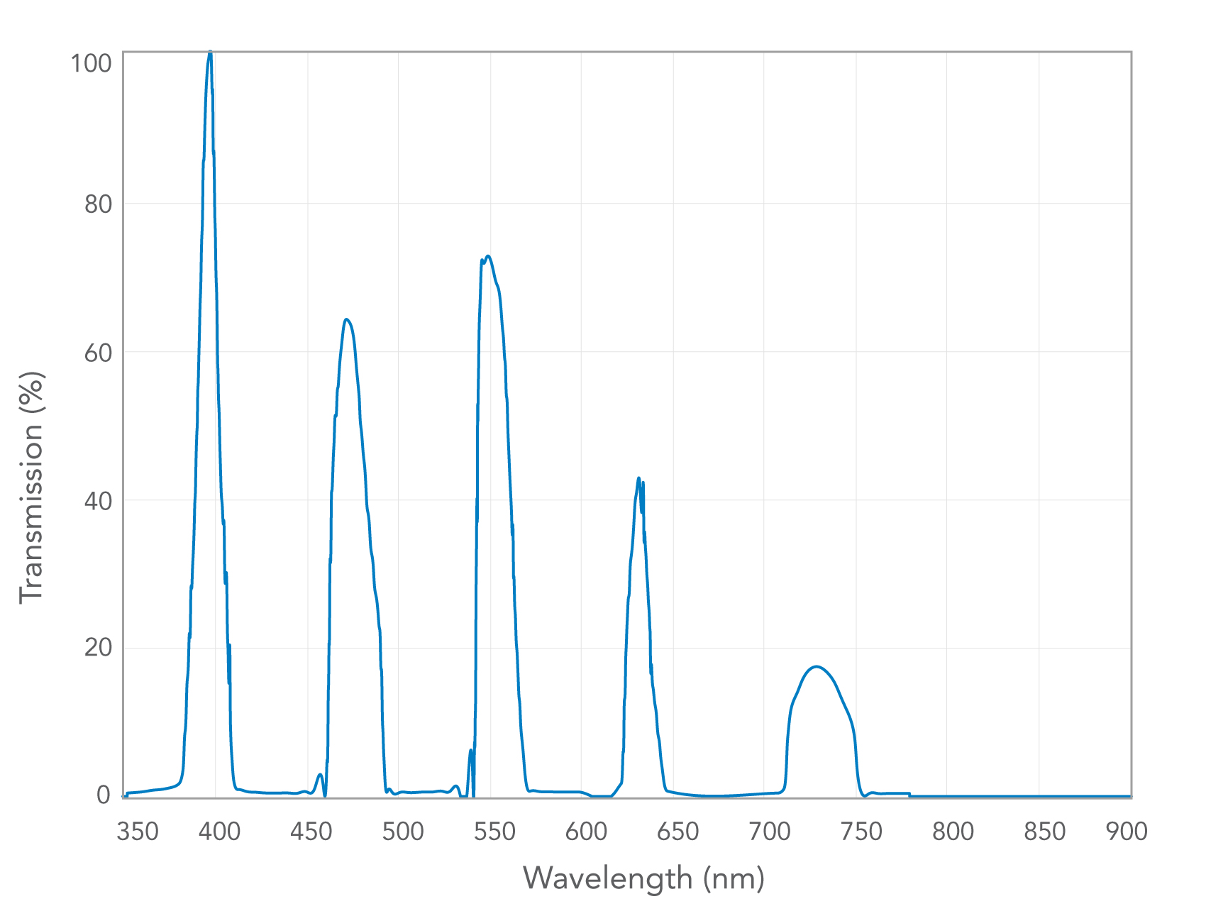 |
Figure 6. When a number of LEDs and fluorophores are used together, excitation crosstalk between channels can be a problem, where the LED from one channel excites a fluorophore from a different channel. Crosstalk should be minimized for the greatest signal-to-noise ratio. | Figure 7. Spectral output of a commercially-available multi-LED source. Addition of a multi-band filter will improve out-of-band blocking and signal-to-noise between the excitation bands. |
Using a broadband source for multichannel fluorescence poses similar problems to the multichannel LED description above. Careful choice of excitation and emission fluorescence filters and fluorophores are required to maximize the SNR in the system.

Semrock Solutions
With one of the largest fluorescence filter catalogs in the industry, IDEX Health & Science | Semrock provides industry-leading performance and quick turnaround for most commercially available illumination sources. We are your go-to source for prototyping and user-replaceable components, but we also have unique custom and high- volume capabilities.

