6-Port Medium Pressure Injection Valves Instruction Guide - Bulkhead Version
What is the Medium Pressure Injection Valve?
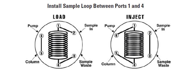
The Medium Pressure Injection Valve is an external sample loop style injector for applications up to 1,000 psi (69 bar). Each port is connected through an internal flow path to the adjacent port. In the “Load” position, the sample loop is loaded through Port 2, while the system flow runs through Ports 5 and 6. When the valve is switched 60 degrees to the “Inject” position, the sample loop is included into the system, and flow goes from Port 5, through the loop and out Port 6. The Bulkhead Mounting Option allows the valve to be panel mounted, for convenience.

Specifications
- Maximum Operating Pressure: 1,000 psi (69 bar)
- Maximum Operating Temperature: 80˚C (176˚F)
- Thru-hole diameter: .040" (V-451); .063" (V-541)
- Port-to-port volume: 5.12μL (V-451); 12.7μL (V-541)
- Wetted materials: Teflon® and Vespel®
Included with the Valve
V-451:
- (6) P-235, PEEK® 1/4-28 nuts
- (6) P-200, ETFE ferrules
- (1) V-104, 5/64" Allen Wrench
V-541:
- (6) P-335, PEEK 1/4-28 nuts
- (6) P-300, ETFE ferrules
- (1) V-104, 5/64" Allen Wrench
Plumbing Diagram

Making an Injection
- Complete loop fill
When the sample loop is completely filled, the injection volume is equal to the volume of the loop and the valve passages. This is the most precise method to inject a sample using these valves. It is recommended to overfill the loop with at least twice the volume of the loop, the excess sample will go to waste out Port 3, and this will insure the loop is completely full. To completely fill the loop, inject the sample through Port 2 while the valve is in the “LOAD” position. Load the sample and when finished, turn to “INJECT” to include the sample loop in the system flow path. - Partial loop filling
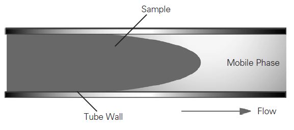
It is not recommended to partially fill a sample loop with more than half of its volume. Due to the laminar flow effect, larger volumes may be lost out of the waste line (Port 3). The laminar flow effect in tubing is depicted below. The average velocity of the sample at the center of the loop can be up to twice the velocity at the walls of the tubing.

Bulkhead Mounting Instructions
- Drill the appropriately sized hole in the bulkhead (see Diagram A).
- Remove the rotary knob from the valve with the included Allen wrench; remove the Mounting Nut and Washer and set them aside.
- Insert the shaft of the new Valve through the bulkhead, aligning the Notch in the bulkhead’s mounting hole with the “Key” on the Valve body (see the Valve pictured in Diagram C). Place the Nut and Washer (removed in Step 2) on the shaft side and tighten, followed by reattaching the Rotary Knob (see Diagram B).


Chemical Compatibility
| Solvent | Vespel® | Teflon® |
| Aromatics | R | R |
| Chlorinated | R | R |
| Ketones | R | R |
| Aldehydes | R | R |
| Ethers | R | R |
| Amines | M | R |
| Aliphatic Solutions | R | R |
| Organic Acids | M | R |
| Inorganic Acids | M | R |
| Bases | NR | R |
| Sulfonated Compounds | M | R |
M Some solvents in this category are satisfactory, others are not. Please review the notes above or contact IDEX Health & Science for further information.
R Recommended.
NR Not recommended
