Introduction to Thin Film Optical Filters
Basic Principles for the Discerning Customer
In this resource article we discuss thin film interference filters, some of the principles behind them, and how IDEX Health & Science uses these principles to design and manufacture its characteristically high quality Semrock® optical filters.
Absorption Filters vs Thin Film Interference Filters
There are two categories of commonly used optical filters: absorption filters and thin film interference filters. Examples of absorption filters include colored glass and the black material used to block the sun’s rays in solar eclipse glasses. Absorption filters are so called because they absorb light, meaning that the light energy is transferred to the atoms of the absorbing material, the light ceases to exist, and the energy is dissipated as heat. Solar eclipse filters absorb all but about one millionth of visible and ultra-violet light, which is enough to allow us to safely get a good view of an eclipse, while avoiding damage to the sensitive tissues of the eye. Other examples of absorption filters include colored plastic bottles and traffic signal lights, which use absorbance to absorb all colors except for the one to be seen.
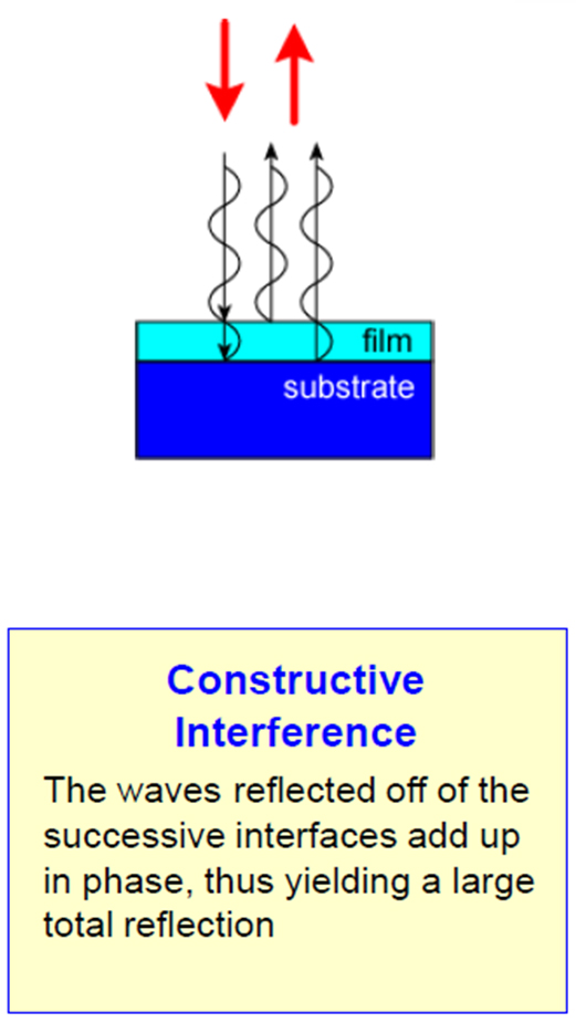
Figure 1
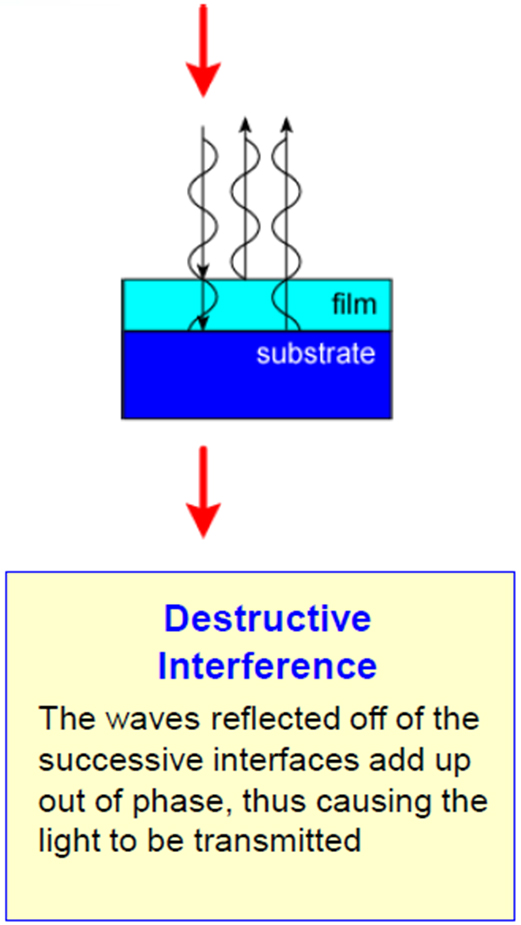
Figure 2
Thin film interference filters, on the other hand, prevent undesired colors from passing through the filter not by absorbing them, but by reflecting them back towards the source. The mechanism used is optical interference, which is based on the wave nature of light. Any color of light has a characteristic wavelength, and when many of these rays are together, they interact with each other, much like waves on water, resulting in what is called interference.
Thin Film Interference Filters
An example of this is seen in Fig. 1, which shows a thin film lying on a different material. Consider first the case of light which we do not want to pass the thin film. This light impinges on the top of the thin film, and some light reflects off it. Some light continues through the thin film and reflects from the second surface, and travels back through the thin film. These two rays of light interfere constructively after they leave the thin film, meaning that their amplitudes add. This happens to all light waves of this wavelength, resulting in all that light being reflected towards the source. Since that reflected wavelength is associated with a specific color, that color is said to be blocked, or rejected, by the thin film.
For other wavelengths of light one can have destructive interference (Fig. 2), meaning that that color of light is passed through the thin film, with no reflected light.
An oil slick on water (Fig. 3) shows these effects. If one looks at the top of the slick, one sees different colors, by which we understand that the slick is also a thin film -- not uniformly thin everywhere, but with varying thickness by location. Some areas of the slick reflect blue light, some green, and so on, depending on which wavelengths are constructively interfering. There are many other examples of thin film interference – watch a soap bubble and notice the different reflected colors. You can also shine a light through a soap bubble onto a white sheet of paper to see the colors that pass through it!
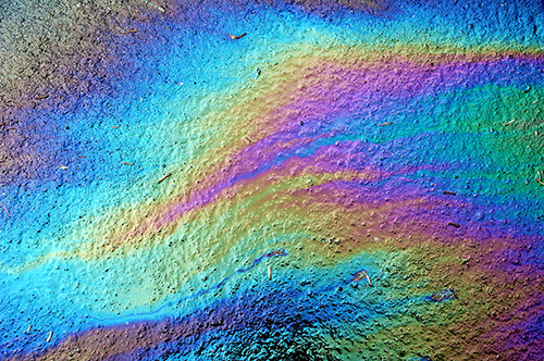
Figure 3
Now that we have established what happens when there is just one thin film, we can describe what happens when there are many thin films in a stack. Suppose we choose a thin film thickness that reflects blue light. If you stack up more of these blue-reflecting thin films, the stack gets better and better at reflecting that blue light. If one has a hundred such layers, one now gets so much reflection of blue light, that one can say that transmission of blue light is blocked, for example by a factor of 1000. This means that only one part in 1000 of blue light passes the filter, and the rest is reflected. This stack is then said to block blue light at the OD 3 level, where 1 OD unit corresponds to a factor of ten, and 3 OD means a factor of 103 = 1000.The next step in this analogy is to imagine a series of layers of different thicknesses, which reflect certain colors of light and transmit others, for example to make a bandpass filter, which blocks all light except for a band of wavelengths. This is referred to as multi-path interference (Fig. 4) and is the result of light interacting with many thin film layers. Instead of just one color being reflected, like in an oil slick, multi-path interference can reflect a broad range of wavelengths, and the response is controlled by the thickness and number of the thin film layers, as well as the materials used in the films themselves.
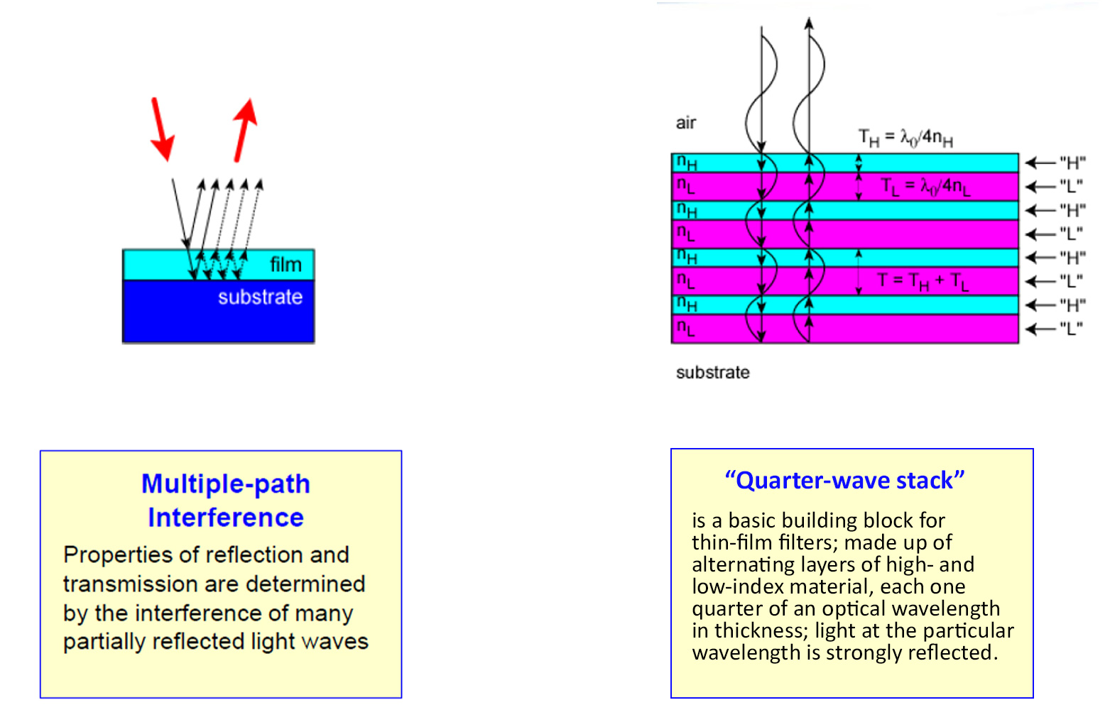
Figure 4
Figure 5
An example of this is seen in Fig. 5, the so-called quarter-wave stack. Different thicknesses, different number of layers, and different materials cause different optical responses such as reflection and transmission. Using multi-path interference theory and applying our deep understanding of our manufacturing process, we design optical filters with “manufacturable specifications, ” meaning that each filter has specified specifications, that those specifications are achieved, and that those filters can be measured to prove they do achieve those specifications.