
Stories & Features


When working with fluidic systems in life science applications—whether in chromatography, diagnostics, or analytical instrumentation—threaded fittings play a critical role in system integrity and performance. Yet, identifying and understanding fitting threads is often overlooked until an issue arises.
This guide walks you through how to identify fitting threads, understand thread standards, and ensure proper selection for reliable fluidic connections.
Most fluidic fittings use standardized thread callouts that provide key information about their geometry. Typically, a thread designation includes two numbers:
For example:
1/4-28 means the fitting has a 1/4-inch diameter and 28 threads per inch (TPI).
Understanding this designation is the first step in selecting compatible components and avoiding leaks, dead volume, or failures in your system caused by fittings.
In fluid handling systems, mismatches between threads can result in:
Identifying threads in fittings is essential to maintaining system performance.
You can often determine thread type with simple tools—a ruler and careful observation.
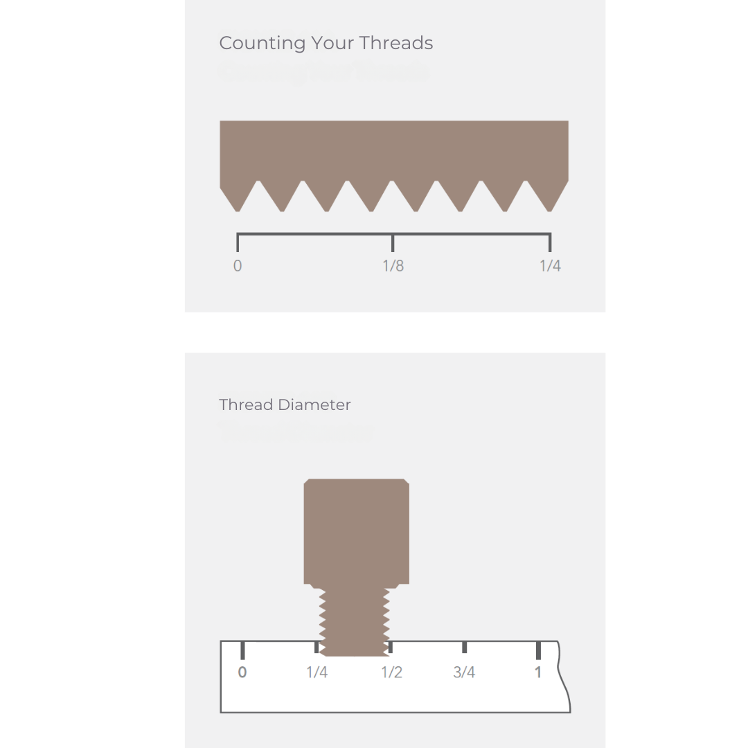
Step 1: Count Threads Over a Known Distance
Important: The first thread is your zero point. Do not include it in your count.
Multiply the number of threads within 1/4 inch by four to calculate threads per inch.
Example:
Step 2: Measure Thread Diameter
Place the fitting against a ruler and measure across the widest point of the threads. This gives you the nominal diameter.
Together, these two measurements define the fitting’s thread specification.
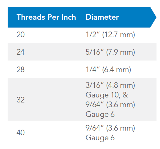
In many chromatography systems, thread diameter and pitch often follow consistent pairings. While exceptions exist, these patterns provide a helpful starting point when identifying fittings.
For example:
Using known industry standards can help narrow down possibilities before confirming measurements.
Metric-threaded fittings are increasingly common in modern fluidic systems. They follow a different convention than imperial threads.
A typical metric designation looks like:
M6 x 1
This indicates:
Key Difference:
The process is similar but uses millimeter measurements:
Step 1: Determine Thread Pitch
For common metric fittings, each thread crest will align consistently with millimeter increments (e.g., 1 mm spacing for M6 x 1). Some fittings may follow different spacing patterns (e.g., 0.7 mm pitch), so look for repeating intervals.
Step 2: Measure Diameter
Measure across the widest part of the threads using the metric scale to determine nominal diameter.
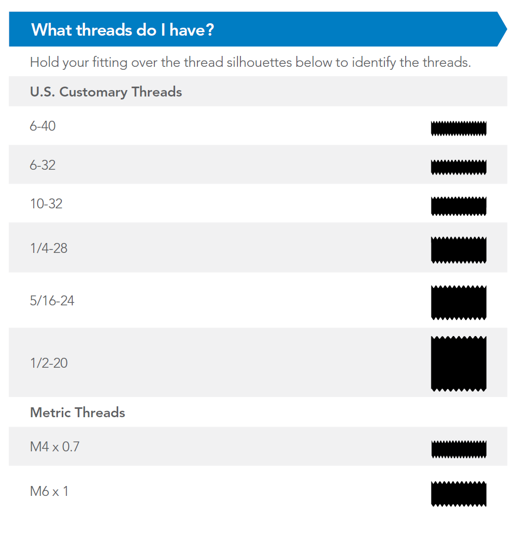
If manual measurement isn’t practical, visual identification tools can help:
Overlaying your fitting against known shapes can quickly confirm thread size and type, reducing trial-and-error during setup.
Download and Print this Thread Measurement Chart at 100%
To ensure optimal system performance:
Thread identification may seem like a small detail, but it has a significant impact on the accuracy, reliability, and longevity of life science instrumentation.
By understanding thread standards and applying simple measurement techniques, you can confidently select fittings that maintain system integrity, supporting consistent, high-quality results across your workflows.
Browse our eStore for fitting types, port design, tubing ID, materials, and diameters.