Stories & Features

Optical filters are critical for precision imaging, fluorescence applications, and laser-based systems, but small miscalculations can lead to signal loss, distortion, or suboptimal performance. Choosing and specifying the correct optical filters is crucial to success in these types of biological experiments. Here are examples of three common optical filter mistakes and how to avoid them.
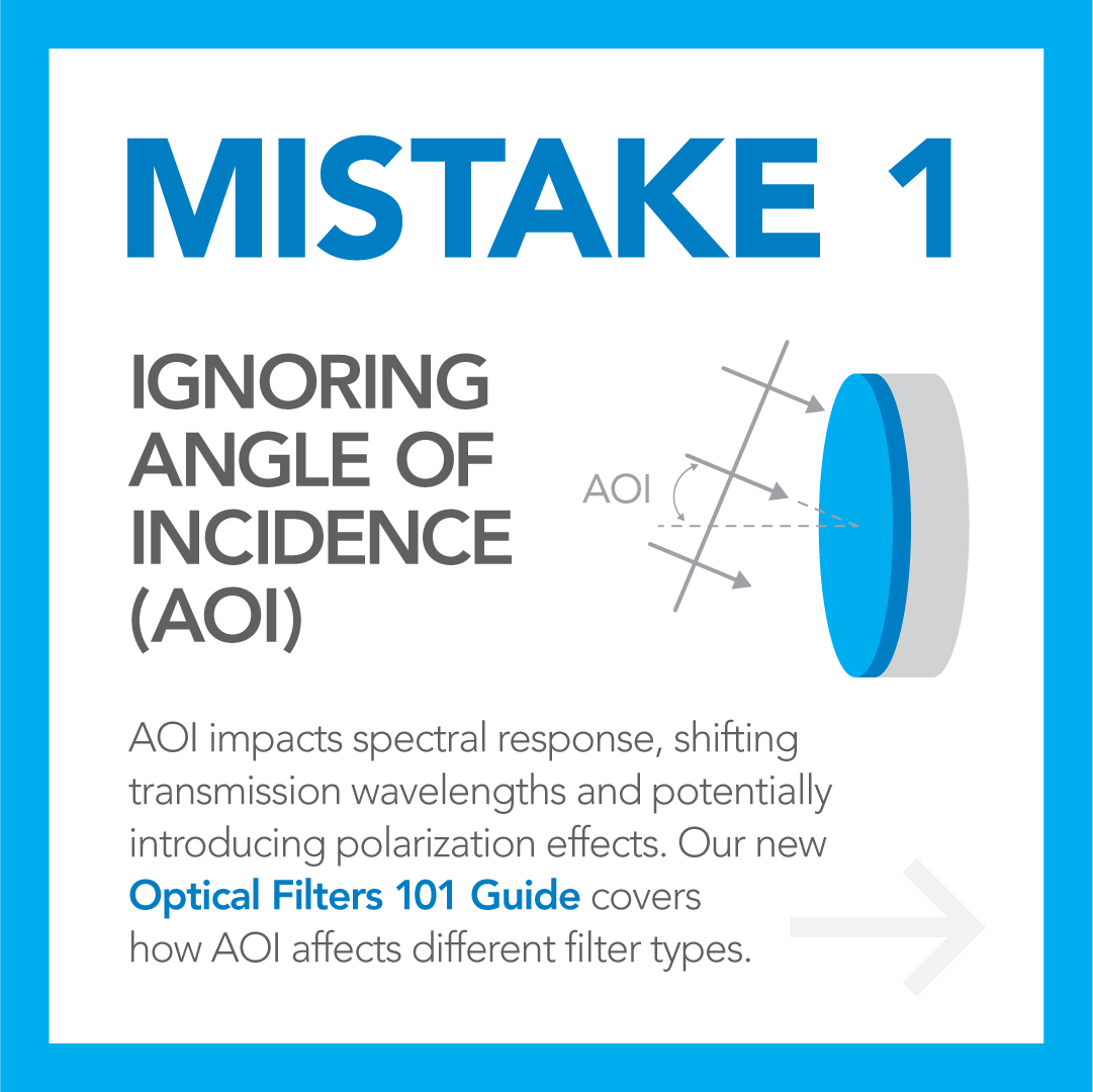
Angle of Incidence, or AOI, is the angle at which a collimated beam of light is incident on the filter’s first surface, measured relative to the surface normal. Collimated light does not converge or diverge, it follows a straight path, creating a beam of light with constant diameter.
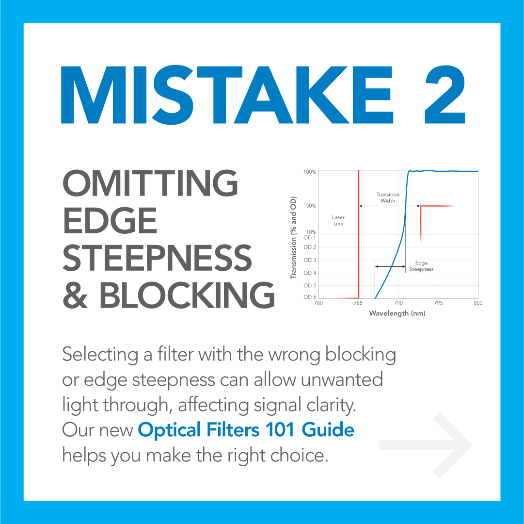
Transition width and edge steepness, while related, have different meanings. Edge steepness is a measured spectral response, while transition width is a performance specification describing the acceptable location of the filter’s spectral curve. Transition width can be thought of as the “goal posts” – a filter’s spectral edge should fall within the specified spectral width. These specifications are important in laser-based experiments, such as Raman, where the laser wavelength is very close to the signal wavelength.
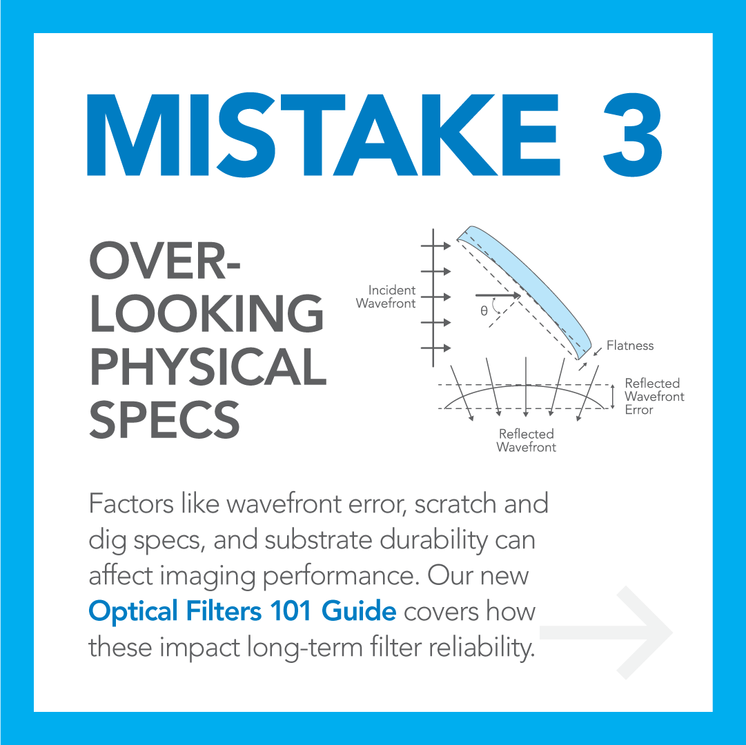
Transmitted Wavefront Error (TWE), expressed in waves, describes the deviation of the filter’s transmitted wavefront from a perfect plane. TWE is caused by the filter’s thickness deviations and material inhomogeneity.
Reflected Wavefront Error (RWE), expressed in waves, describes the deviation of a wavefront from a perfect plane after being reflected from the filter. It is caused by surface curving and irregularities.
Scratches (S) and digs (D) are commonly specified together and noted as S/D. S specifies the maximum allowable scratch width in microns. D specifies the maximum allowable size of holes, bubbles, and other defects in the films. Digs are specified in units of 10 microns, so a dig spec of 40 = 400 microns in diameter. Note that scratch and dig specifications only apply within the CA of the filter.