Comprehensive Guide to Check Valves: A Critical Component of HPLC Pumps
Overview
Check valves (CV) are integral components of a High-Performance Liquid Chromatography (HPLC) Pump. This one-way valve allows fluid to flow through in only one direction by preventing backflow. There are several types of check valves, with the ball / seat configuration being one of the most common for HPLC pump applications. In this configuration, the ball makes a seal when seated on the complementary spherical sealing surface of the seat component. Most ball / seat check valves use gravity or reverse flow to create a seal. Check valves are critical to HPLC pump performance, as they prevent any backflow and ensure maximum pumping efficiency. The right combination of the design parameters, including material selection based on application needs, are critical to the performance of the check valve.
History and Introduction to the HPLC System
The development of check valves used in chromatography can be traced back to the first automated amino acid analyzer developed at the Rockefeller Institute in 1958. On the heels of that instrument, the work of Csaba Horvath, at Yale University in 1965, led to the development of the modern high performance liquid chromatograph.
An understanding of the range of applications of HPLC pumps and their evolution is reflected in the design considerations for the check valve, utilized to ensure proper pump operation, precision, and accuracy.
HPLC column resins evolved from 10-micron irregularly shaped particles to smaller, more spherical particles, creating the need for pumping systems that could handle high pressure and require high precision. The evolution of HPLC columns led to variation in requirements for pump designs, and over the years has created different requirements for check valves.
Over time, HPLC pumps evolved from single piston pumps to a single pump having as many as three or four pistons to achieve delivery of the mobile phase. This progression emulated HPLC systems that used high volume syringe drives to deliver solvents to the HPLC column in a single piston pass (Isco, Perkin Elmer®, etc.). These syringe style pumps have long been the “gold standard” for pulse-free, low flow noise mobile phase delivery.
The goal of today’s HPLC pumping systems is to deliver solvents smoothly while using as few pistons and check valves as possible. One critical characteristic in HPLC pump design is the duration of the pump’s intake stroke, versus the duration of the delivery stroke. The target flow rate of the pump and the maximum designed pressure rating for the pump system are both important aspects that affect the check valve design for a given implementation.
Generally, high pressure is applied to the outlet check valve of the pump when mobile phase is delivered to the column. Therefore, flow restriction in the outlet check valve contributes only minuscule back pressure relative to the overall system pressure. However, the operation of this check valve is critical to the overall pressure rise and fall presented to the HPLC column and chromatographic injection valve. If the check valve allows pressure relief in the form of backflow into the pump, the column will experience large pressure swings as the pump reengages and forces flow forward once again.
For an LC pump inlet check valve, the pump’s intake stroke speed and the volume drawn into the head are critical factors in check valve design, along with the viscosity, vapor pressure, and atmospheric gas load of the target mobile phases. These criteria must be considered when properly designing an inlet check valve. When an inlet check valve fails, changes to the volumetric delivery of the dispense occurs, adversely affecting system pressure, system flow rate (pump accuracy), and pump efficiency.
Single Versus Double Ball Seat Check Valve
Check valves come in various sizes, configurations, and materials to accommodate for ideal flow rate, material compatibility, and pressure requirements of the HPLC application.
The cartridge (check valve body) shown to the right in Figure 1 can have an imprinted flow arrow on the outside of the body to illustrate the intended direction of mobile phase flow. The cartridge can house a single or double ball based on instrument manufacturer preference. Typically, the check valve will have two identical polymer end caps for sealing on either end. The ball cage can act as the CV body as well, as illustrated in Figure 1.
In a double ball / seat style check valve (Figure 2), the ball cage is a separate component from the body. The body of the check valve here is a tube to hold the internal components. It is important for the integrity of the check valve that the critical dimensions of the design features ensure a good seal and prevent the end caps from bottoming out. The body can be a polymer, metal, or hybrid material (PEEK-Lined Stainless Steel) based on the HPLC application need. Customers typically use a double ball seat check valve for redundancy to help alleviate or delay replacement. The second ball / seat can act as a back up to the first.
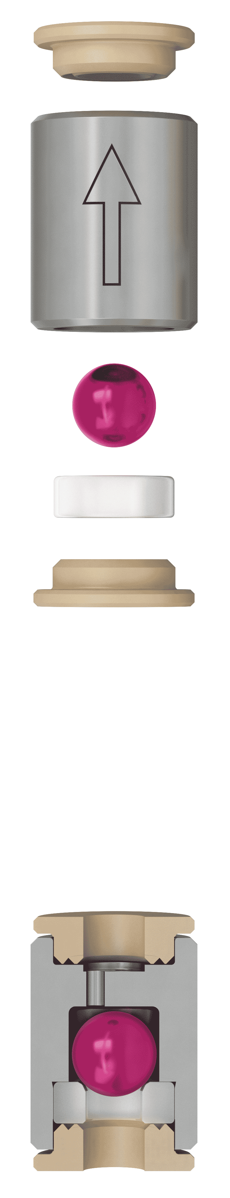
Figure 1: Single 1/8” ball cartridge, with an exploded view.
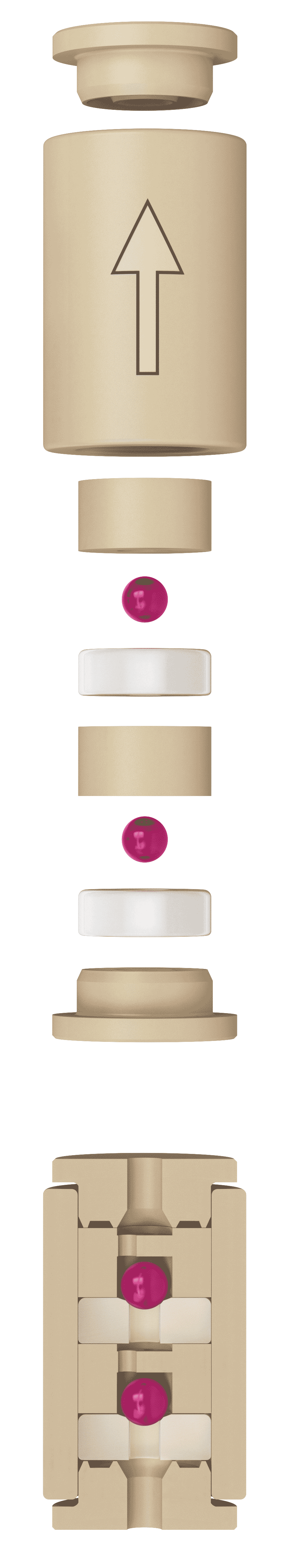
Figure 2: Double 1/16” ball cartridge, with an exploded view
Critical Attributes of a Check Valve
There are a few critical check valve attributes that have an impact on the performance of the pump, based on the pressure and chemical compatibility requirements of the HPLC application. Some of these are important for pressure handling and others are critical for compatibility with specific solvents.
Ball Seat Material
Many different ball and seat materials have been used over the years. Materials such as ruby, sapphire, alumina, and zirconia (YTZP) have been utilized for various applications. Due to material hardness requirements and the need for chemically inert wetted surfaces, the most common ball / seat material combination is a ruby ball on a sapphire seat. Materials can vary depending on system requirements. For higher pressure applications, metal or metal-lined components are typically used.
Ball Size and Grade
Check valve balls have varying sizes and grades. Ball materials can be ruby, sapphire, or ceramic, based on the application requirements. Ball sizes typically vary from 1/16” to 1/8” in diameter and, depending on the material, vary in grade as well. The ball size is complementary to the mating components’ ID specifications to facilitate the flow / pressure requirements. Ball grade is the numerical value of the diameter tolerance per ball expressed in micro inches (µin). The grade of the ball determines how tight the tolerances are on diameter and surface condition. The lower the grade number, the tighter the tolerances and better the finish.
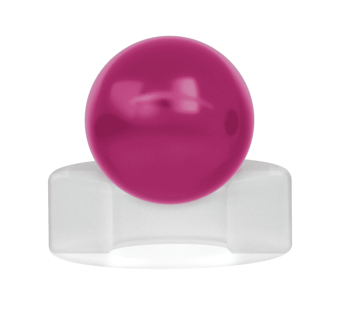
Figure 3: Optimal placement for ideal sealing surface area.
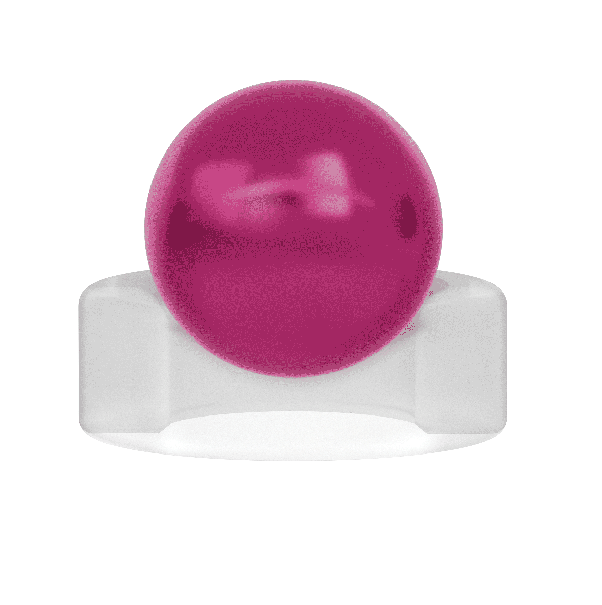
Figure 4: Imperfect seal with ball wedged into the seat ID.
Figure 5: Imperfect seal with ball too far above the sealing surface.
Ball Height
The ball height defines how much ball travel is allowed between sealing and open positions of the check valve. Height is measured in relation to the sealing surface of the seat, and it has an impact on the functionality of the check valve. The importance of ball positioning on the seat is dependent on two factors: the ability to create a seal and the ability to remove that seal. To achieve this balance, one should strive for the maximum sealing surface area and the least amount of sticking potential (Figure 3). When the center of the ball is able to wedge far into the seat, sticking may result (Figure 4). When the ball is further above the sealing surface (Figure 5), the less likely it is to stick. When varying the ball height, the sealing surface area also changes. The ideal ball height can be controlled by varying the design features of the seat ID, ball size, and sealing surface dimensions to ensure a good seal and prevent sticking potential.
Ball Movement
The ball cage controls the volume around the ball as well as how much distance the ball can travel during operation. There should be enough space above the ball so it can lift off the seat and allow for solvent to flow through. More space above the ball can result in reduced response times because the ball must travel a longer distance to re-seat after opening. Minimal space on the sides of the ball is also recommended to help reduce lateral movement. However, flow restriction during the intake stroke of the pump must be considered. The ball cage should not interfere with the ball movement and neither is it desirable for the ball to have much room to shift laterally (off-axis) which can either delay or prevent re-seating, impacting the amount of reverse flow required to re-seat the ball. This is especially important for gravity operated check valves, which must seal quickly to stop the backflow of dispensed solvent back into the pump and potentially to the solvent reservoirs. Gravity-operated check valves will unavoidably have a small amount of back flow until they seal, yet they must withstand pressure fluctuations between dispense cycles. Examples of different ball cage designs are illustrated in Figure 6 and Figure 7, below.
Figure 6: Three hole design.
Figure 7: Off center single hole
Sealing Surface of the Ball Seat
The sealing surface of the seat is where the ball makes contact as the check valve closes. This area is crucial to the performance of the check valve, as the ball must make a circular contact all the way around. Seat diameter is very important to check valve performance. A large sealing surface may cause micro leaks due to multiple points of contact on the seat. A large sealing surface can also “grab” the ball more than intended and cause a higher cracking pressure. Cracking pressure is the minimum upstream pressure required to lift the ball off the seat and open the check valve enough to allow flow. Inversely a small sealing surface may not be sufficient to make a seal or hold the ball in place. Some check valve designs have an edge or a chamfer to make a seal. This edge could deform over time and cause leaks. Some sealing surfaces are made by using a concave spherical radius that matches the size of the mating ball.
Ideal surface conditions are also important for the proper functionality of the check valve. For instance, machine marks from coarse surface finishing can cause micro leaks. This is especially detrimental if the marks are all in one direction, creating a leak path across the sealing surface. The check valve component raw materials can also vary in porosity and grain structure which can impact the sealing surface area. External factors may also impact check valve sealing by physically preventing or delaying the check valve sealing against its seat. Common external factors include contamination, flow restrictions, solvents, and mobile phase outgassing. All of which must be balanced to create check valve sealing surfaces that ensure high performance and decreased maintenance issues.
Torque
As mentioned earlier, depending on the application, the check valve cartridge holder can be made of metal or polymer. The critical design areas are all around the cartridge pocket / counter-bore. In order to ensure a seal before the holder bottoms out, the pocket depth should be shallow compared to the overall length of the mating cartridge / components.
Lack of proper design tolerances can cause the check valve assembly to leak and can result in over-torquing, which further causes problems such as:
- The threads on the holder can gall in the mating component threads and may prevent removal.
- Crushing the cartridge may appear like the ball is sticking, but the over torqued assembly could force the ball into the seat to the point that it cannot liftoff the seat to be opened again.
A properly designed check valve cartridge holder creates a shelf where the holder will bottom out at some point and seal the check valve cartridge to the pump body without limiting the motion of the ball in the cartridge. A good design practice for check valve cartridges utilizes polymer end caps which act as a sealing surface for the check valve.
Check valves designed with PEEK end caps can hold higher torque as compared to those designed with softer end cap materials like PFA, which tend to be more sensitive to over-torque, causing deformation and leaks.
Check Valve Sticking Concerns
One of the most important field concerns with the check valves is the sticking issue when using solvents. Sticking can be defined as higher than normal pressure required to lift the ball off the seat. Inlet check valves in chromatography pumps must open with a very small differential pressure across the check valve as the piston intake stroke begins. Since an inlet check valve is operated by gravity and driven by atmospheric pressure, sticking of the inlet check ball to the seat can be detrimental to pump operation by limiting the amount of mobile phase entering the pump piston area.
There are several reasons that can cause the check valve to stick. The sealing surfaces of the components may develop a film over time that causes the surfaces to be extremely smooth. This can result in a ringing effect which causes the ball to require higher pressures to open the check valve. This is more common when using Acetonitrile (ACN) with ruby / sapphire check valves. The most effective remedy is to ultrasonically clean the check valve to remove the film.
Sticking can also be caused by contamination or debris in the system. This type of sticking typically generates a different film or deposit that acts as an adhesive, keeping the ball stuck on the seat. Certain salty buffers can develop a crystalline deposit when the check valve dries out (due to evaporation or inactivity). In this case, the check valve may have to be thoroughly cleaned or replaced to address the issue. With cleaning, even if the ball dislodges, the system could experience a significant increase in back pressure or fail to reach the desired pressure or flow.
A third possible cause of sticking occurs when the ball becomes wedged in the seat. We reviewed this in the “Sealing surface of the Ball Seat” section above, and this can happen due to several reasons, including over-torquing, ball / seat material selection, or the geometry of the seat and sealing surface being incorrect for the application. In this case, the ball is not actually sticking, but is being forcefully wedged into the seat to the point where it cannot be lifted.
Alternatively, if debris or deposits develop in the check valve, it can result in an opposite effect where the debris can disrupt the sealing surface, causing micro leaks to occur and subsequently cause excessive pressure ripple effects. If the deposits are sufficiently large, the leak may be significant enough that the check valve will no longer close.
Salty buffers from some HPLC mobile phases can crystallize on the ball and seat when allowed to dry or when caused to precipitate from solution by switching mobile phases without thoroughly rinsing the flow path. Either drying out or precipitation of these salty buffers will result in the check valve sticking and malfunctioning. It is important to have a scheduled preventative maintenance cycle and never allow the cartridge to dry out from inactivity when using harsh solvents. Best practice would be to thoroughly clean the check valve and allow it to dry, before leaving it unattended for a longer period of time. Ultrasonic cleaning of the internal components is also recommended. As an example, highly concentrated sodium chloride attacks stainless steel, causing visible amounts of crystallization. This results in leak paths on sealing surfaces between the ball and seat. Images in Figures 8 to 11 illustrate crystallization when the cartridge dries out after use of a mobile phase containing sodium chloride.
Figure 8: Crystallization in the ball cage
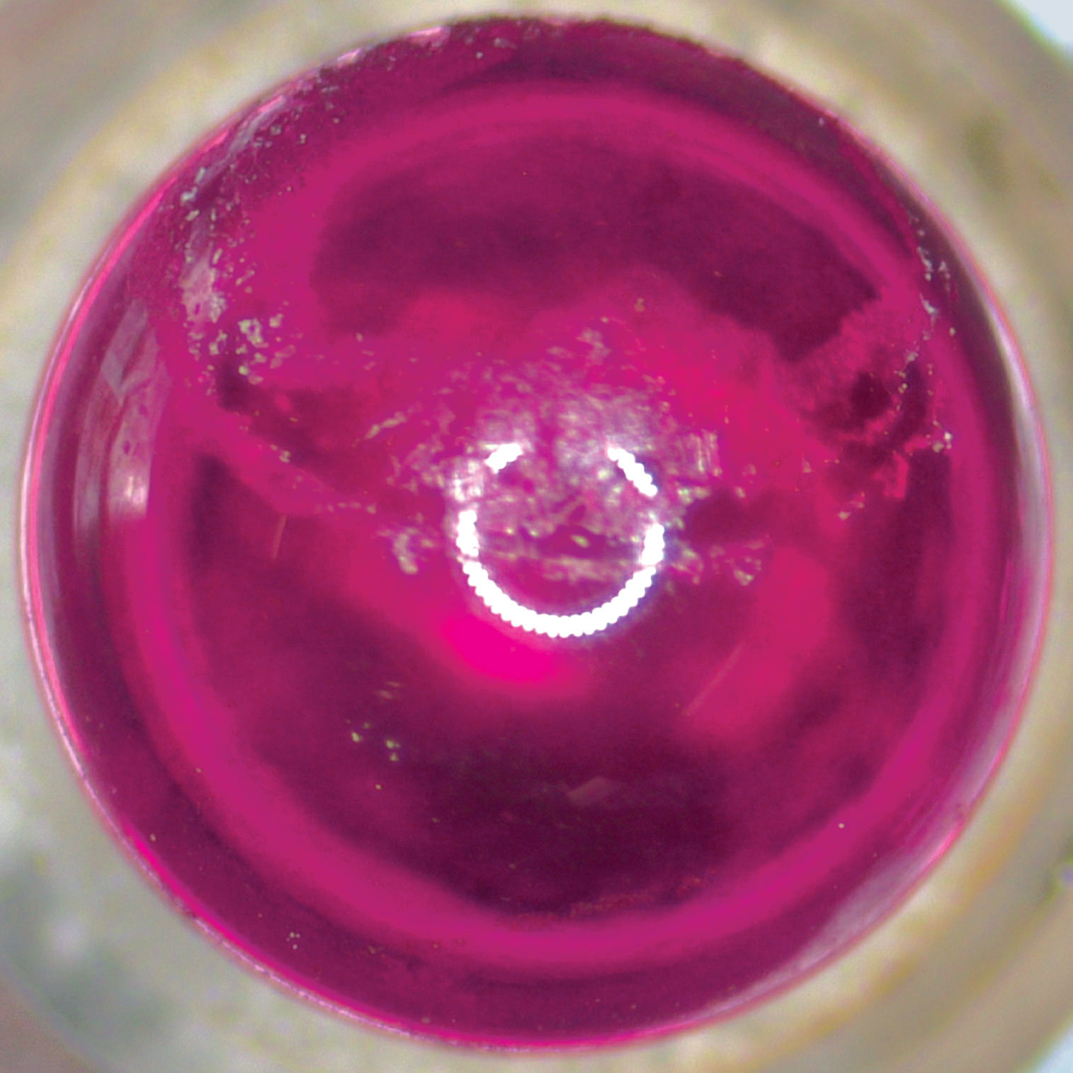
Figure 9: Film coating causing sticking
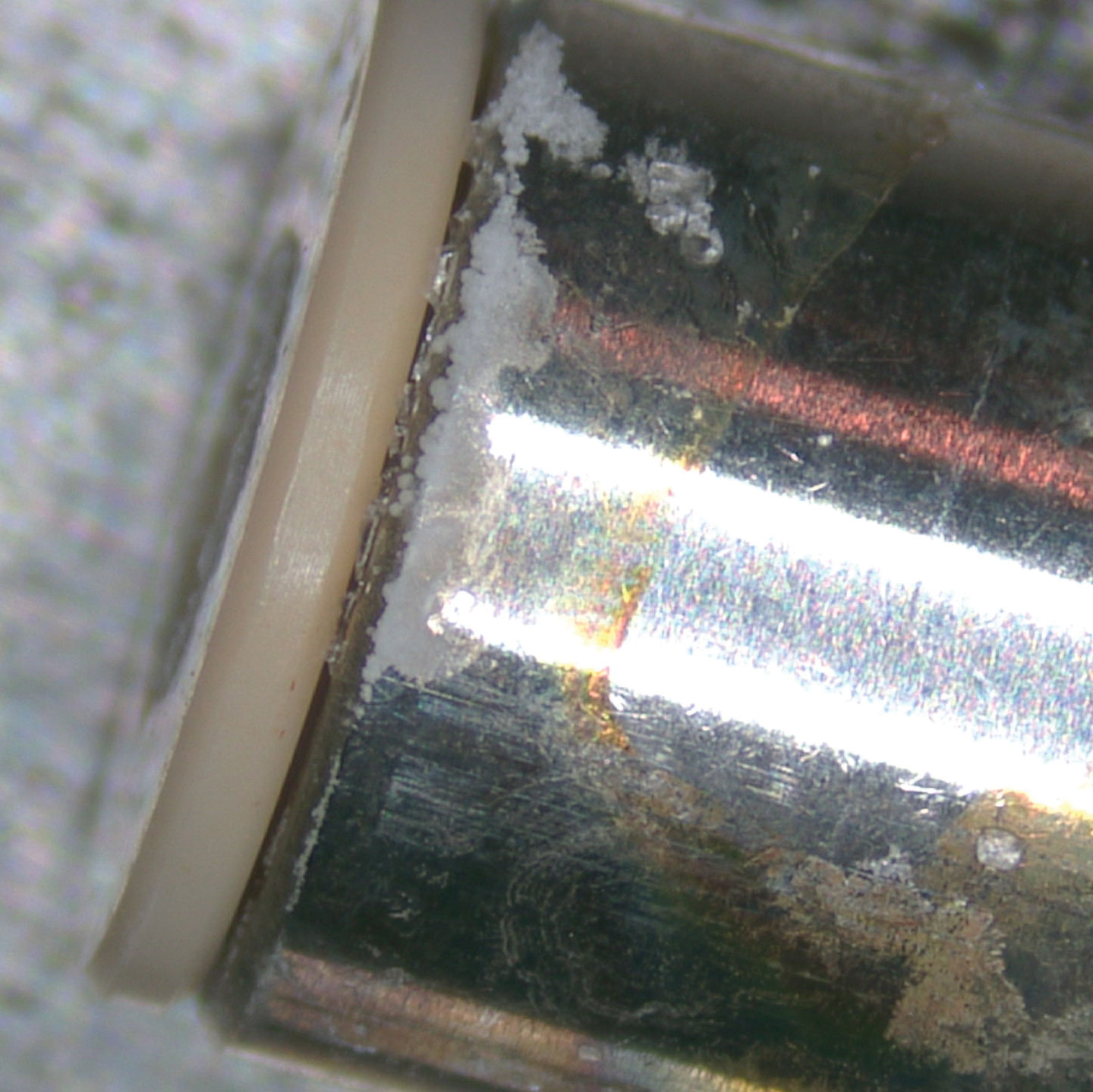
Figure 10: Salt crystallization on the cartridge
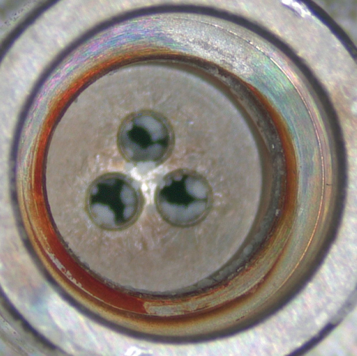
Figure 11: Crystallization in the ball cage thru-holes.
Damage to the cartridge from salty reagents can be minimized by cleaning the check valves prior to drying. The images below show the benefits of just a quick rinse of water after using a mobile phase containing sodium chloride (see Figure 12 and Figure 13).
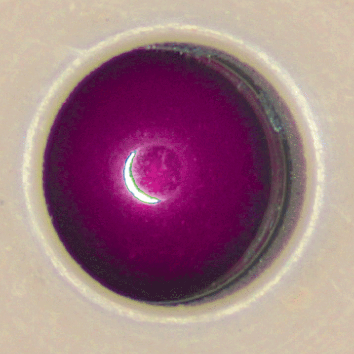
Figure 12: Minimal crystallization from rinsing
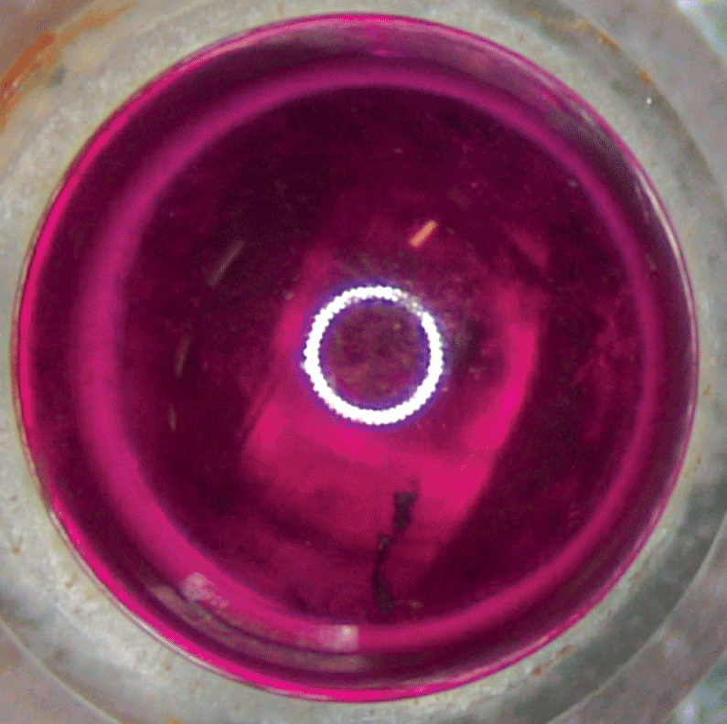
Figure 13: Minimal crystallization from rinsing
Another example of crystallization can be seen with sodium bicarbonate when not rinsed (see Figure 14 and Figure 15).
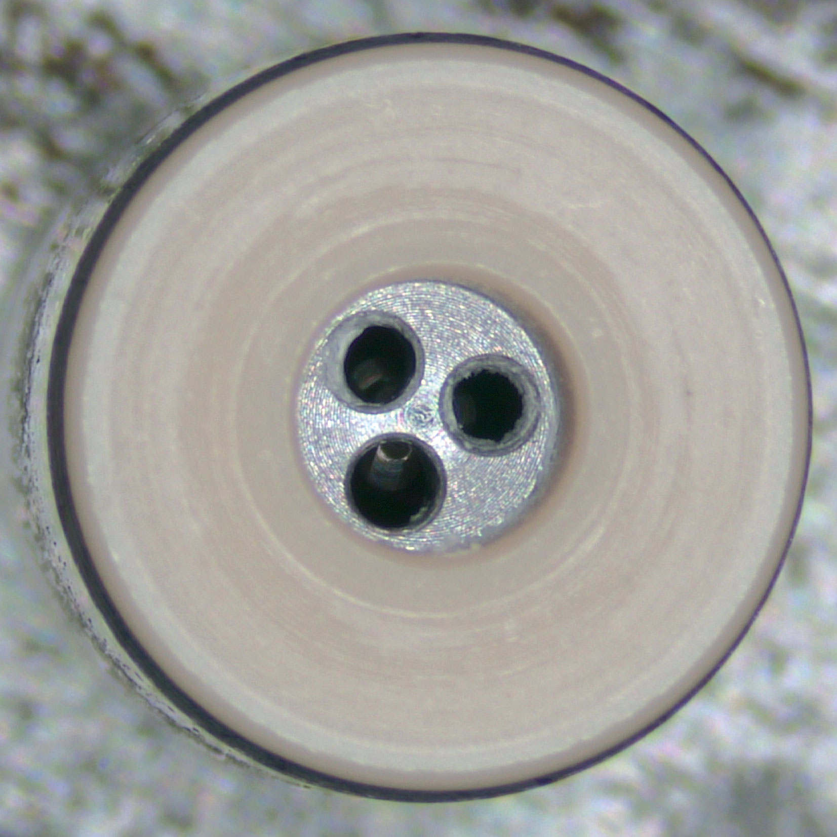
Figure 14: Crystallization in ball cage
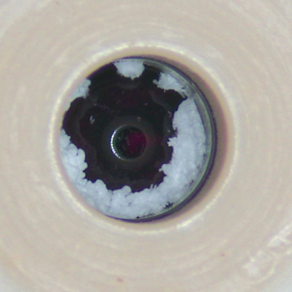
Figure 15: Crystallization in seat ID
Another interesting sticking phenomena can be seen in Figures 16 and 17, below. When using acetonitrile, the check valve will appear normal and not show signs of corrosion or crystallization. However, the acetonitrile will form a smooth film on the sealing surfaces resulting in a very polished appearance. This acetonitrile film causes the ball to stick to the seat. Even when horizontal or upside down (shown below) the ball and seat will stick.
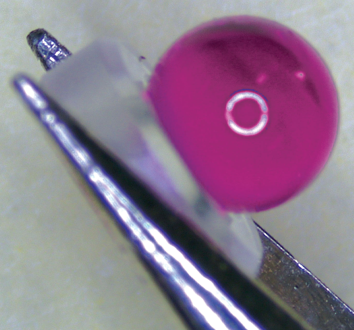
Figure 16: Ball seat sticking
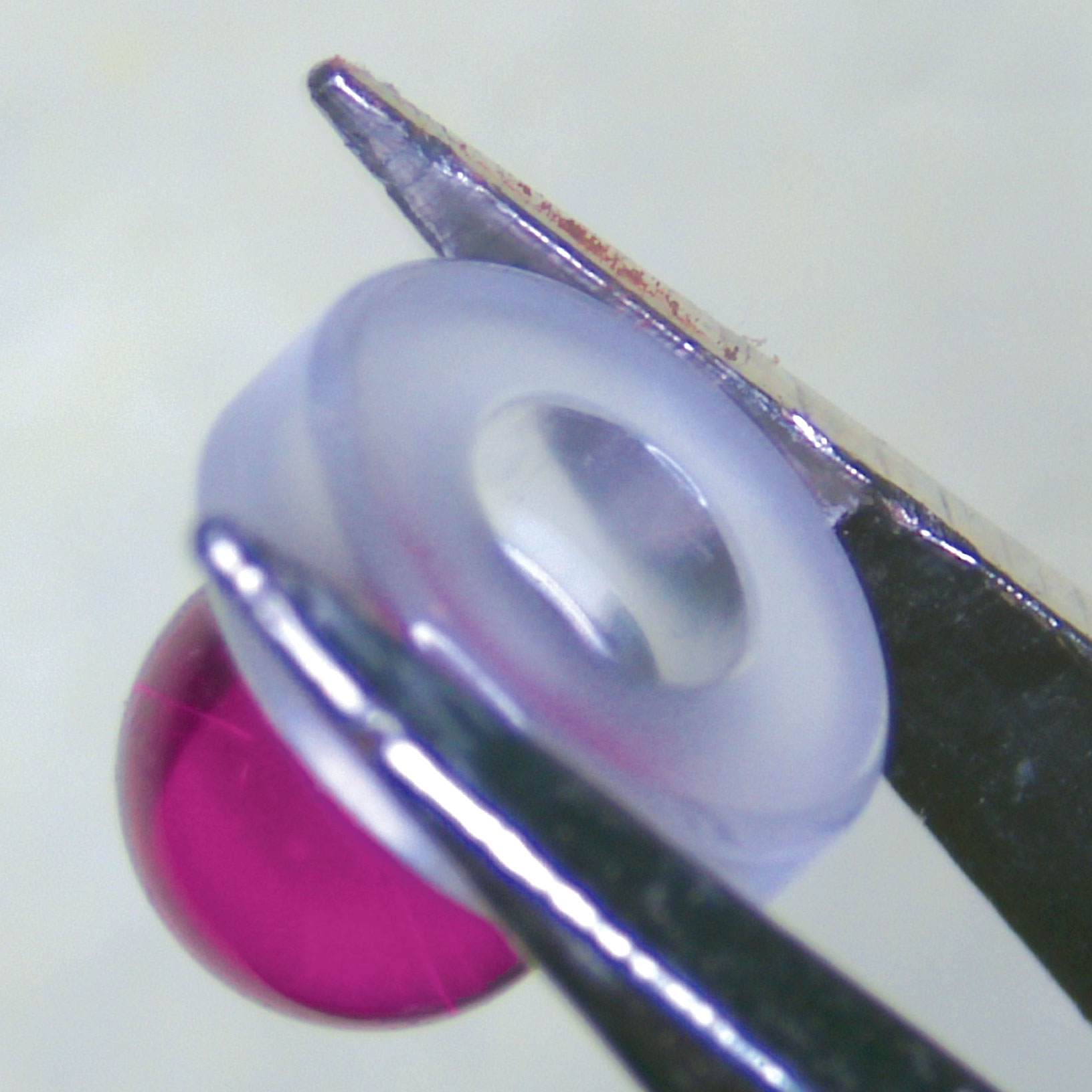
Figure 17: Adheres when upside down.
Performance Characteristics of a Check Valve
Pressure Ripple
Pressure ripple is the variation in pressure delivered by the pump over a given cycle. The pressure ripple can be calculated by finding the difference between the highest (peak) and lowest (valley) pressure values during a pump cycle. A pressure ripple greater than 1% can have negative impact on pump performance and affect the chromatographic baseline. Several factors can increase the pressure ripple percentage, including a small leak caused by contamination or residue on the sealing surface, whereas a sticking ball will have the inverse affect and cause the pressure to spike before the ball is lifted.
Flow Technology
Various tools can be used to optimize check valve design and its fluid path. Pressure drop across the check valves cartridge is one of the most common concerns with customers. Computational Fluid Dynamics (CFD) can be used to analyze the fluid movement characteristics and to optimize check valve designs virtually. CFD helps characterize fluid flow and identify less optimal designs before critical parts are manufactured, avoiding unnecessary time and expense. CFD simulations help ensure manufacturing tolerances are understood and will not have a negative impact on the performance of the check valve. To illustrate the value of CFD, the image in Figure 18 shows a check valve cartridge with virtually no pressure drop at a given pressure and flow rate depicting constant high pressure in red across the length of the CV cartridge. All the internal components can be modified to increase and decrease flow restrictions within the check valve.
The image on the right (Figure 19) shows that restricting the ball cage design causes the total volume in the flow path to increase the pressure drop greatly. This shows the pressure differential across the length of the CV cartridge dropping considerably from high pressure in red at the inlet, to lower pressure in blue at the outlet, illustrating that the flow restriction or turbulence can cause outgassing of the dissolved atmosphere and interfere with the operation of the inlet check valve when the mobile phase is not sufficiently degassed. With known specifications such as pressure drop, operating pressure, and flow rates, we can optimize the check valve design to meet the specific requirements. CFD can also help determine whether certain features are critical to a custom design or if they can be eliminated to reduce component cost / complexity.
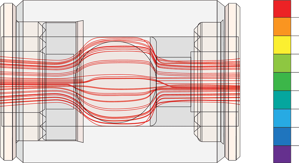
Figure 18: Optimized ball cage design ensures uniform pressure drop.
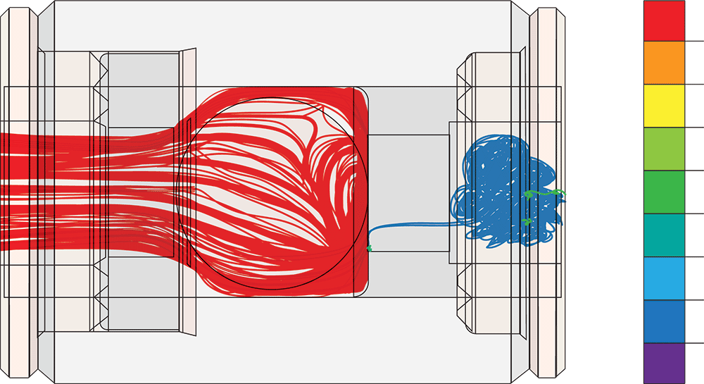
Figure 19: Restricted ball cage design increases pressure drop
Conclusion
This white paper covers the critical elements related to the functional performance of a check valve and ultimately the overall chromatography results. It is critical to customize the design of the appropriate check valve to meet the specific application needs. Having metal components will help cater to higher-pressure capabilities but could negatively impact solvents if the application is sensitive to the metals. Ball positioning and movement will have an impact on pressure ripple percentage.
Perhaps the most important features are the critical dimensions of the sealing surfaces. CFD is a valuable tool that can be leveraged for optimizing the fluid path and minimizing pressure drop across the CV cartridge. Depending on the style of check valve, picking the appropriate torque is necessary to ensure a good seal without compromising the internal components. In addition to the design elements, having a proper maintenance plan is critical to extend the check valve longevity as well as maintain the performance of the pump and other components, especially when using harsh buffers and solvents. At IDEX Health & Science, we understand the impact of all these attributes to the optimal functionality of a check valve and its impact to the preventative maintenance cycle.
IDEX Health & Science designs ball seats and check valves used in wide range of chromatography applications. We have hard material manufacturing capabilities and equipment with capabilities of holding dimensional tolerances up to 10-millionths of an inch (0.00001”) and surface tolerances less than 1 micron for sapphire and ceramic seats and synthetic ruby balls. Each of our check valves are 100% tested in a Class 1000 Clean Room.
With our design expertise, we leverage the right attributes to manufacture a check valve that meets the platform needs in a cost-effective manner by keeping design for cost central to our discussions.
Authors:
Dave Medeiros, Saba Jazeeli, David Steckman, Eric Beemer, and Carl W. Sims